m), lightweight (1.4 kg) device incorporating a video camera with an infra-red source and an infra-red sensor. The infra-red sensor measures the reflection of infra-red light by objects in front of the camera and calculates 3D position data for those objects. Recent accuracy tests have indicated that the device is capable of calculating position data with an accuracy of approximately 1 cm (Dutta 2012). The software supplied with the Kinect uses pattern recognition to detect landmarks of interest, such as limb segments and joint estimations.
In the system developed in this chapter, the Kinect is used to capture joint center locations for the shoulder, elbow and wrist for the calculation of shoulder and elbow joint angles. It is not possible to use the Kinect for the calculation of wrist and hand joint angles due to accuracy limitations in hand tracking when the device is at the distance required to produce a large enough field of view for all the other segments. Instead, an electrogoniometer is included to collect wrist angle data and an optional data glove can be used to capture individual finger joint angle data.
FES surface electrodes are positioned over the patient’s anterior deltoid, triceps and wrist and hand extensor muscles, with placement following clinical guidelines. A series of 5 V, 40 Hz pulses are produced by the control hardware for each channel and amplified by a four-channel electrical stimulator to generate a bi-phasic signal which achieves a smooth muscle contraction (de Kroon et al. 2005). For safety, the maximum pulsewidth that can be applied to any channel is limited within the control software and also by the stimulator. Prior to any session, the amplification level for each channel is set by applying a constant stimulation signal with pulsewidth  s from the control hardware and slowly increasing the voltage until the maximum comfortable level is reached. During subsequent tests the pulsewidth is limited to
  s.
s.
s from the control hardware and slowly increasing the voltage until the maximum comfortable level is reached. During subsequent tests the pulsewidth is limited to s.The electrode array is formed by  elements that can each be routed to one of four FES channels through use of custom made controlled multiplexor hardware, comprising an Arduino board and shift register array. For each required hand and wrist posture, the optimal electrode sites and associated FES pulsewidths are selected during initial tests through a search procedure involving local linear model identification and gradient-descent optimization. The sites are then fixed during subsequent experiments, with the pulsewidth amplitudes controlled by ILC. Figure 6.1 shows the electrode array and data glove and the control system block diagram is again that of Fig. 5.5.
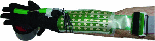
elements that can each be routed to one of four FES channels through use of custom made controlled multiplexor hardware, comprising an Arduino board and shift register array. For each required hand and wrist posture, the optimal electrode sites and associated FES pulsewidths are selected during initial tests through a search procedure involving local linear model identification and gradient-descent optimization. The sites are then fixed during subsequent experiments, with the pulsewidth amplitudes controlled by ILC. Figure 6.1 shows the electrode array and data glove and the control system block diagram is again that of Fig. 5.5.Fig. 6.1
Electrode array with data glove and electrogoniometer used for stimulating and tracking hand and wrist movement
The system software incorporates tracking of the patient’s movement with the control schemes implemented to mediate the FES in real-time. A custom made C++ application is used to read the arm and hand positions from the Kinect, electrogoniometer and (if used) data glove. Position data are then transferred to the real-time control hardware (dSPACE ds1103) that implements ILC laws involving embedded dynamic models of the arm. Outputs of the control law comprise pulse-width modulated (PWM) signals for each of the FES stimulator channels, together with RS232 serial data to control the electrode array. Digital inputs and outputs are also employed to interface with the instrumented task objects. Figure 6.2 shows a signal flow diagram.
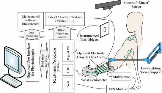
Fig. 6.2
Signal flow diagram
A graphical user interface (GUI) has been developed to enable the user to customize control parameters, implement the FES control, collect position outcome data, select the task details to be performed and review performance after each session.
6.2 Control Design and Evaluation
6.2.1 Human Arm Model
A dynamic model of the arm-support system incorporates a biomechanical description of the human arm and a representation of the SaeboMAS spring support. Position values for the shoulder, elbow and wrist joint centers are calculated using the Kinect. To assist the FES actuated control law, a simplified model of the arm is used for the calculation of joint angles. Figure 6.3 shows the kinematic model of the human arm.
Spasticity in stroke patients often restricts flexion of the shoulder in the antero-posterior plane, extension of the elbow and extension of the wrist and fingers (Levin 1996). Therefore, the anterior deltoid, triceps and wrist and hand extensor muscles were selected for stimulation. It is assumed that stimulation applied to the triceps produces movement about an axis perpendicular to the upper and forearm segments and that stimulation applied to the wrist and hand extensors produces movement about an axis that is fixed with respect to the forearm. For the anterior deltoid it is assumed that stimulation produces movement about an axis that is fixed with respect to the shoulder and determined by two rotation transformations. These comprise rotations around the z-axis by  and around the x-axis by
  . Identification of
  and
and  is described below.
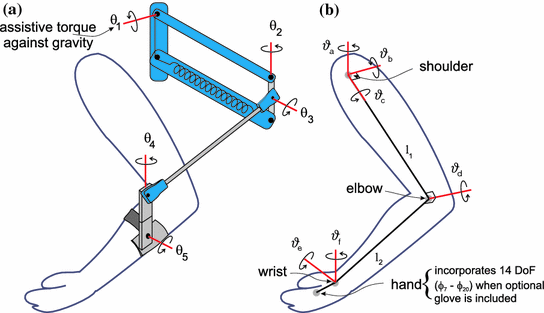
and around the x-axis by . Identification of and is described below.Fig. 6.3
Kinematic model of the a SaeboMAS support and b human arm
The dynamic model of the human arm is

![$$\begin{aligned} q_{u} = \left[ \begin{array}{cccccc} \vartheta _{a}&\vartheta _{b}&\vartheta _{c}&\vartheta _{d}&\vartheta _{e}&\vartheta _{f} \end{array} \right] ^{T} \end{aligned}$$](/wp-content/uploads/2016/09/A306304_1_En_6_Chapter_Equ38.gif) where
where  and
and  are
are  inertial and Coriolis matrices, respectively,
  and
and  are friction and gravitational vectors and
  comprises the moments produced through application of FES. These moments are of the form
![$$ \tau (u, q_{u},\dot{q}_{u}) = \left[ \begin{array}{cccccc} \tau _{a}(\vartheta _a, \dot{\vartheta }_a, u_a)&0&0&\tau _{d}(\vartheta _d, \dot{\vartheta }_d, u_d)&\tau _e(\vartheta _e, \dot{\vartheta }_e, u_e)&0 \end{array} \right] ^T $$](/wp-content/uploads/2016/09/A306304_1_En_6_Chapter_Equ39.gif) where
where  ,
,  and
and  represent the electrical stimulation applied to the anterior deltoid, triceps and wrist and hand extensor muscles, respectively, with
 ![$$u = \left[ \begin{array}{cccccc} u_a&0&0&u_d&u_e&0 \end{array} \right] ^{T}$$](/wp-content/uploads/2016/09/A306304_1_En_6_Chapter_IEq18.gif) and the same muscle model as in the previous chapters. Finally, h is a vector of externally applied force and torque comprising components
and the same muscle model as in the previous chapters. Finally, h is a vector of externally applied force and torque comprising components  due to the spring support and
  due to interaction with objects and
  is the system Jacobian.
(6.1)
and are inertial and Coriolis matrices, respectively, and are friction and gravitational vectors and comprises the moments produced through application of FES. These moments are of the form, and represent the electrical stimulation applied to the anterior deltoid, triceps and wrist and hand extensor muscles, respectively, with and the same muscle model as in the previous chapters. Finally, h is a vector of externally applied force and torque comprising components due to the spring support and due to interaction with objects and is the system Jacobian.The SaeboMAS support structure dynamics are of the form

where  and
and  are
are  inertial and Coriolis matrices and
![$$ q_{r}= \left[ \begin{array}{ccccc} \theta _1&\theta _{2}&\ldots&\theta _5 \end{array} \right] ^{T} $$](/wp-content/uploads/2016/09/A306304_1_En_6_Chapter_Equ40.gif) represents the angles of the spring support. In addition,
represents the angles of the spring support. In addition,  is the system Jacobian, and
  and
and  are friction and gravitational vectors. The vector
  comprises the moments produced through gravity compensation provided by the spring, which takes the form
 ![$$\left[ \begin{array}{ccccc} k_1(\theta _1)&0&0&0&0 \end{array} \right] ^T$$](/wp-content/uploads/2016/09/A306304_1_En_6_Chapter_IEq29.gif) . Also the rigid connection between structures gives rise to a bijective mapping between
. Also the rigid connection between structures gives rise to a bijective mapping between  and
and  and hence the combined model is given by

This model of the arm is used by the FES control law to produce an input signal that results in accurate completion of the tasks. During trials incorporating FES, the law assists tracking about  ,
,  and
and  alone, and it is assumed that the patient has sufficient control over the remaining axes to adequately perform the task. Due to the complexity of identifying the parameters in a full dynamic model of the hand and wrist, the array element identification procedure uses stimulation and angular output data from the glove to construct a linear model linking these variables (Freeman 2014). The resulting representation is then integrated with a simpler model of the hand and wrist (Soska et al. 2013) detailed next.
(6.2)
and are inertial and Coriolis matrices and is the system Jacobian, and and are friction and gravitational vectors. The vector comprises the moments produced through gravity compensation provided by the spring, which takes the form . Also the rigid connection between structures gives rise to a bijective mapping between and and hence the combined model is given by(6.3)
, and alone, and it is assumed that the patient has sufficient control over the remaining axes to adequately perform the task. Due to the complexity of identifying the parameters in a full dynamic model of the hand and wrist, the array element identification procedure uses stimulation and angular output data from the glove to construct a linear model linking these variables (Freeman 2014). The resulting representation is then integrated with a simpler model of the hand and wrist (Soska et al. 2013) detailed next. 6.2.2 Hand and Wrist Model
A possible control scheme for the hand and wrist is shown Fig. 6.4. In control terms, this is a highly coupled system with each joint actuated by at least two muscle groups: flexor and extensors. Furthermore, most of the hand muscles are either bi-articular or multi-articular, i.e., they actuate simultaneously two or more joints. The muscles of the hand are divided into two groups: intrinsic i.e., originate solely in the hand and extrinsic, i.e., located proximally in the forearm. Although it is possible to stimulate individual intrinsic and extrinsic muscles of the hand, e.g., using embedded electrodes, in most of the FES systems considered in the literature only the extrinsic muscles are stimulated. The approach taken in this monograph is to investigate feasibility of surface electrode array stimulation of extrinsic muscles, which hence avoids the need for surgery and makes the approach cost effective and suitable for widespread uptake. A simplified model of the hand is developed next and used in control law design.
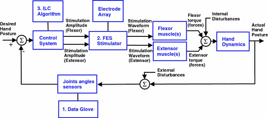
Fig. 6.4
FES schematic for hand and wrist rehabilitation
The model developed includes a single composite finger, representing the combined action of four fingers, wrist and neglects the thumb orientation. The finger and wrist are modeled as a 3-link rigid body system, consisting of 3 active revolute joints as shown in Fig. 6.5. This still provides an accurate representation of the hand since  of the functional movements of the hand involve the four fingers moving together (Ingram et al. 2008). Link 1 represents the II-V Metacarpal bones connected by the wrist joint, Links 2 and 3 represent proximal and middle phalangeals of the finger connected by the Metacarpal-Phalangeal joint (MCP) and Proximal-Interphalangeal joint (PIP) respectively.
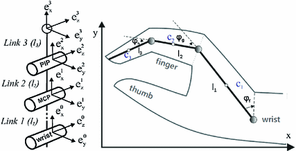
of the functional movements of the hand involve the four fingers moving together (Ingram et al. 2008). Link 1 represents the II-V Metacarpal bones connected by the wrist joint, Links 2 and 3 represent proximal and middle phalangeals of the finger connected by the Metacarpal-Phalangeal joint (MCP) and Proximal-Interphalangeal joint (PIP) respectively.Fig. 6.5
Planar hand model
The dynamic model of the finger/wrist is formulated using Lagrangian analysis and can be written in the form

where  is the inertia matrix,
  denotes the centrifugal and Coriolis forces,
  is the vector representing gravitational force and the generalized co-ordinates are
 ![$$q_{f} = \left[ \begin{array}{ccc} \vartheta _{f}&\vartheta _{g}&\vartheta _{h} \end{array} \right] ^{T}.$$](/wp-content/uploads/2016/09/A306304_1_En_6_Chapter_IEq39.gif) During purely horizontal movement of the finger, gravity can be neglected.
During purely horizontal movement of the finger, gravity can be neglected.
(6.4)
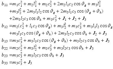
is the inertia matrix, denotes the centrifugal and Coriolis forces, is the vector representing gravitational force and the generalized co-ordinates are During purely horizontal movement of the finger, gravity can be neglected.The inertia matrix is
![$$\begin{aligned} B_{f}(q) = \left[ \begin{array}{ccc} b_{11} &{} b_{12} &{} b_{13}\\ b_{21} &{} b_{22} &{} b_{23}\\ b_{31} &{} b_{23} &{} b_{33} \end{array} \right] \end{aligned}$$](/wp-content/uploads/2016/09/A306304_1_En_6_Chapter_Equ41.gif) where
where
 where
where  kg,
kg,  kg,
kg,  kg are the masses,
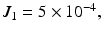
 are inertias (kg m
 ) and the assumed lengths (m) are

 and
and 
kg, kg, kg are the masses, are inertias (kg m) and the assumed lengths (m) are and The entries in  are
are
\\- & {} [(m_{2} l_{1} c_{2} + m_{3} l_{1} l_{2}) \sin {\vartheta _{g}} + m_{3} l_{1} c_{3} s_{12}](2 \dot{\vartheta }_{f} \dot{\vartheta }_{g} + \dot{\vartheta }_{g}^{2})\\ c_{21}= & {} [(m_{2} c_{2} l_{1} + m_{3} l_{1} l_{2}) \sin {\varTheta _{2}} + m_{3} c_{3} l_{2} s_{23}] \dot{\vartheta }_{h}^{2} \\- & {} m_{3} c_{3} l_{2} \sin {\vartheta _{h}}(2 \dot{\vartheta }_{g} \dot{\vartheta }_{h} + \dot{\vartheta }_{g}^{2})\\ c_{31}= & {} [m_{3} c_{3} l_{2} \sin {\vartheta _{g}} + m_{3} c_{3} l_{1} s_{23}]\dot{\vartheta }_{g}^{2} + m_{3} c_{3} l_{2} \sin {(2 \dot{\vartheta }_{g} \dot{\vartheta }_{f} + \dot{\vartheta }_{f}^{2})} \end{aligned}$$](/wp-content/uploads/2016/09/A306304_1_En_6_Chapter_Equ43.gif) where
where  Also
Also  is the vector of moments produced by the application of FES and
  is the vector of frictional components acting about each joint of the form
![$$\begin{aligned} F_{f}(q_{f}, \dot{q}_{f}) = \left[ \begin{array}{c} k_{1}(\vartheta _{0,f} - \vartheta _{f}) - b_{1} \dot{\vartheta _{f}}\\ k_{2}(\vartheta _{0,g} - \vartheta _{g}) - b_{2} \dot{\vartheta _{g}}\\ k_{3}(\vartheta _{0,h} - \vartheta _{h}) - b_{3} \dot{\vartheta _{h}} \end{array} \right] \end{aligned}$$](/wp-content/uploads/2016/09/A306304_1_En_6_Chapter_Equ5.gif)
where 
 and
and  are the viscous friction coefficients (Ns/m). It is assumed that the muscle groups that actuate each joint produce a stiffness that can be represented by a spring with zero elongation at the initial position
  and stiffness coefficients
 (N/m).
are Also is the vector of moments produced by the application of FES and is the vector of frictional components acting about each joint of the form(6.5)
and are the viscous friction coefficients (Ns/m). It is assumed that the muscle groups that actuate each joint produce a stiffness that can be represented by a spring with zero elongation at the initial position and stiffness coefficients (N/m).Figure 6.6 shows the musculoskeletal structure of the finger and wrist included in the model. The wrist joint is assumed to be actuated by three extensor muscles: Extensor Communis (EC), Extensor Carpi Radialis Longus (ECR) and Extensor Carpi Ulnaris (ECU). The muscles of the finger act through a complex tendon network, termed the extensor mechanism. This network is approximated by a longitudinally symmetric tendon rhombus, consisting of active and the passive tendons, as also shown in Fig. 6.6.
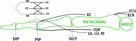
Fig. 6.6
The musculo-tendon structure of the wrist and finger
The extensor mechanism of the finger is modeled in the same manner as Theodorou et al. (2011) and includes 5 active tendons, driven by independently controlled muscles: the Flexor Digitorum Profundus (FDP), the Extensor Digitorum Communis (EC), the Ulnar and Radial Interosseous (UI and RI), the Lumbrical muscle (LU), and 3 passive tendons: the Radial Band (RB) the Ulnar Band (UB) and the Extensor Slip (ES).
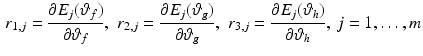
Electrically stimulated muscles of the hand contract, generating pulling forces that produce finger/wrist movement. The transformation from muscle force vector, y, with dimension m to the p-dimensional net joint torque,  , at the finger/wrist joints can be defined as in Valero-Cuevas (2009), yielding
where
![$$\begin{aligned} R(q_{f})= & {} \left[ \begin{array}{ccc} r_{11} &{} \ldots &{} r_{1m}\\ \vdots &{} \ddots &{} \vdots \\ r_{p1} &{} \ldots &{} r_{pm} \end{array} \right] \end{aligned}$$](/wp-content/uploads/2016/09/A306304_1_En_6_Chapter_Equ7.gif)
![$$\begin{aligned} y(u, q_{f}, \dot{q}_{f})= & {} \left[ \begin{array}{c} y_{1}(u_{1}, l_{1}, \dot{l}_{1})\\ \vdots \\ y_{m}(u_{m}, l_{m}, \dot{l}_{m}) \end{array} \right] \end{aligned}$$](/wp-content/uploads/2016/09/A306304_1_En_6_Chapter_Equ8.gif)
and each entry in  is the signed scalar moment arm value that transforms a muscle force into torques at the various joints it crosses. Moreover, entry
  in
in  can be evaluated by differentiating the excursion (displacement) E of the jth tendon with respect to the ith joint angle, i.e.,
Excursion of the FDP is modeled (Landsmeer 1955) as
where  is the distance from the straight section of the tendon to the tendon constraint along the line perpendicular to the axis of the bone and
  is the corresponding angle rotation. The term
  is the distance along the axis of the bone from the end of the straight section of the tendon to the joint center.
, at the finger/wrist joints can be defined as in Valero-Cuevas (2009), yielding(6.6)
(6.7)
(6.8)
is the signed scalar moment arm value that transforms a muscle force into torques at the various joints it crosses. Moreover, entry in can be evaluated by differentiating the excursion (displacement) E of the jth tendon with respect to the ith joint angle, i.e.,(6.9)
(6.10)
is the distance from the straight section of the tendon to the tendon constraint along the line perpendicular to the axis of the bone and is the corresponding angle rotation. The term is the distance along the axis of the bone from the end of the straight section of the tendon to the joint center.Tendon excursion of the EC is a function of the wrist and MCP with the addition of the displacement, transformed to the PIP joint through the extensor mechanism