Sterile Instruments/Equipment
- On-table traction
- Towel bumps
- 5.0-mm Schanz pins for manipulative joysticks
- Femoral distractor
- Ball-spike pushers
- Shoulder hook/bone hook
- Steinmann pins
- K-wires and wire driver/drill
- Reamers
- Implants
- Intramedullary nail
- Reconstruction versus condylomedullary
- Large fragment locking or nonlocking plate
- Intramedullary nail
Patient Positioning
- Supine on fully radiolucent table, with a folded towel bump or bolster under the ipsilateral hip and flank, acknowledging spine injuries and stabilizing appropriately.
- Bump can be one or two rolled blankets, but one is typically adequate.
- If bump is too big, lateral imaging can be difficult.
- Bump can be one or two rolled blankets, but one is typically adequate.
- Position patient in a slight “C” position with shoulders centered on table and the affected hip brought as far as possible to the side, preferably overhanging the edge of the table slightly to provide access to the starting point.
- A traction apparatus can be secured to the end of the table and draped into the sterile field (Fig. 16-1).
Figure 16-1. A “traction post” fashioned from a pipe bender is applied to the end of the operating table to allow for an on-table axial lower extremity traction that is easily removable.
- A tensioned distal femoral traction pin (5/64-inch or 2.0-mm K-wire) is placed at the level of the superior pole of the patella as anteriorly as is possible to allow space to pass the guide wire/nail (Figs. 16-2 and 16-3).
Figure 16-2. A 2.0-mm smooth Steinmann pin is placed at the level of the superior pole of the patella, just posterior to the anterior distal femoral cortex to allow for nail passage.
Figure 16-3. With the traction post mounted, and the distal femoral traction pin in place, a sterile traction bow and rope are used to achieve traction. Weights are placed to hang from the rope distally off the traction post.
- Alternatively, use a femoral distractor to restore length prior to nailing. 1
- Place a radiolucent foam ramp under the leg to elevate and assist with lateral imaging.
- Nailing without use of traction table has several advantages:
- Ease of positioning in polytrauma patients
- Simplified imaging
- Access to opposite leg for comparison of length and rotational alignment
- Circumferential access to limb with unlimited ability to manipulate leg to archieve reduction or starting point
- Avoids pressure complications from perineal post
- Ease of positioning in polytrauma patients
- Prior to prepping, place ramp under the contralateral limb and obtain comparison images to assist with rotational reduction. 2
- With C-arm in full lateral position (beam parallel to the floor), rotate the leg to obtain a perfect lateral view of the knee (superimposed posterior femoral condyles) and save the image.
- While holding this exact limb rotation, rotate the C-arm up 90 degrees (beam perpendicular to the floor) and shoot AP image of the hip.
- Center on the lesser trochanter, and magnify the lesser trochanter. Save this image.
- Alternatively, while holding the same limb rotation, obtain a cross table lateral image of the femoral neck (so that the neck’s axis is co-linear with the proximal femoral diaphysis). This will correspond to the angle of femoral version (anteversion). Obtain the magnitude of this angular measurement from the C-arm’s rotational orientation.
- Use radiolucent ruler to accurately identify proper length (Fig. 16-4).
- With C-arm in full lateral position (beam parallel to the floor), rotate the leg to obtain a perfect lateral view of the knee (superimposed posterior femoral condyles) and save the image.
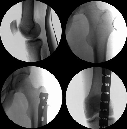
Figure 16-4. Contralateral fluoroscopic views are used to profile the lesser trochanter to ensure proper rotation of the fractured femur (top row). The uninjured limb is also used for length assessment (bottom row).
Implant and Reduction Techniques
- Percutaneous guides permit a small incision (3 to 4 cm) for nail insertion.
- Use a guide wire to locate piriformis fossa.
- It is helpful to have the guide wire collinear with the femoral shaft on both views (Fig. 16-5).
Figure 16-5. The piriformis fossa starting point is localized with a guide pin on the AP and lateral views.
![]()
- If the starting point is correct on both the AP and lateral views, but the wire’s insertion angle is not optimal, a smaller cannulated drill can be used to “swallow” the guide wire (such as from the hip screw instrument set) and then the drill can be used to correct the insertion angle since it is stiffer and can provide a more controlled correction of angulation.
- For proximal fractures, use the lateral view to assist with direction of drilling for the starting point.
- The projection of the endosteal surface under the vastus tubercle on the C-arm can assist the surgeon in directing the guide wire. The drill/wire should be parallel to this endosteal surface (Fig. 16-6).
Figure 16-6. The posterior aspect of the vastus ridge (arrow heads) can be visualized on the lateral view and can be used to guide wire insertion vector.
- An accurate starting point minimizes the proximal femoral stresses during nail insertion, and can minimize iatrogenic fractures caused when the stiff nail is directed toward the medial, anterior or posterior cortex.
Related posts:

Stay updated, free articles. Join our Telegram channel


Full access? Get Clinical Tree


