Engineering Techniques for Implant Design and Evaluation
Thomas D. Brown
Mechanical measurements and mechanical analyses form much of the information base for contemporary hip reconstruction. Orthopedists often are called on to make decisions that draw heavily on data that have been collected using advanced mechanical engineering techniques. Unfortunately, orthopedic training normally includes little or no exposure to the operational principles of contemporary mechanical engineering instrumentation, so it sometimes is difficult for surgeons to appreciate the limitations of data collected from complex laboratory models that use these technologies. The purpose of this chapter is to outline the technical basis for the major classes of mechanical measurements and analyses currently utilized to plan and/or evaluate hip reconstructions.
In laboratory physical testing, many experimental preparations involve application of functionally representative loadings at the whole-construct level, together with the use of sensors to measure deformations, strains, loads, and stresses at specific sites. As a practical matter, the development of construct-level load application systems represents a compromise between clinical realism and cost/complexity, usually resolved in favor of the latter. Logistical compromises also often govern the choice of mechanical sensors, compounded by size constraints, measurement complexity, and signal transduction artifact. Finally, differing levels of abstraction are employed to represent the host bone or joint, including the use of human cadaver material, artificial bone surrogates of several types, and other species in the case of in vivo models.
Mathematical analyses also have found broad application in the study of hip implants, because the underlying physical principles of Newtonian mechanics lend themselves well to description in mathematical terms. The main advantage of the mathematical approach is that, once the model has been developed and (hopefully) validated, individual variables can be very easily isolated and perturbed, allowing systematic and economical study of how constructs respond to changes of individual physical or material factors. Digital computational approaches—especially finite element models—have proven especially useful in that regard. However, mathematical models can be no more realistic than the input data (geometry, material properties, loading conditions) with which they are supplied. And, although physical spot checks and clinical validation are very reassuring when available, it is important to appreciate the major simplifications and limitations of the underlying theoretical framework.
Sometimes it is possible to make the pertinent mechanical measurements directly from patient materials, such as clinical imaging studies or autopsy retrievals. Here, clinical realism is seldom an issue, but a trade-off is that the nature of the available information often compromises mechanical measurement rigor. And, there normally is a much greater degree of variability than occurs under controlled laboratory conditions. Nevertheless, providing insight into in vivo behavior is the ultimate goal of most experimental and computational simulations of total hip arthroplasty (THA) biomechanics. The limits of current understanding of the precise environment in the hip joint of living patients therefore also impact the clinical reliability of biomechanical assessments.
Mechanical Sensors
Probably the most widely used sensor, either for direct application by the end user or as the functional element in manufactured transducers, is the bonded resistance strain gauge. Originally devised in the 1930s (1), these are expendable units that consist of patterned films, usually of copper or constantan (a copper-nickel alloy), deposited by a photo-etching process on a thin plastic backing. Typical footprint sizes of the functional portion of the gauge (gauge width and gauge length) (Fig. 44.1) range from 2 to 6 mm. The underside of the gauge is glued (usually by cyanoacrylate) directly to the substrate whose strain is to be measured. Therefore, as the substrate surface deforms during load application, the foil pattern of the gauge deforms with it. The functional portion of the grid of the gauge consists of a multiple elongated S pattern, typically with several dozen repetitions transversely. As the gauge is stretched longitudinally (x direction in Fig. 44.1) by substrate deformation, each of the strands becomes slightly longer and thinner, thereby very slightly increasing the total electrical resistance.
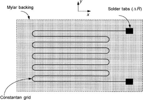 Figure 44.1. Schematic diagram of a bonded resistance strain gauge. A multiply looped metal grid (usually constantan, a copper-nickel alloy) is deposited on a plastic backing. When the gauge is attached to a substrate whose strain is to be measured, the metal grid undergoes the same deformation as the substrate. If the gauge is stretched in its longitudinal direction (here, denoted by x), its electrical resistance increases. This resistance increase ΔR (measured between the solder tabs) can be sensitively detected by means of a Wheatstone bridge circuit. |
When connected to a simple resistance imbalance detection (Wheatstone bridge) circuit, gauge strain can be converted to an analog voltage, and it can be subsequently amplified for recording or display. Gauges as manufactured are in effect precalibrated, in that their ratio of relative resistance change to relative length change (known as the gauge factor) is supplied by the vendor on a batch-specific basis (2). Given known settings of the Wheatstone bridge electrical parameters, knowledge of the gauge factor allows the user to read absolute strain values of the substrate surface without the need for in situ calibration. Of course, since single-element strain gauges are intended to measure strain in the direction of their S legs (x direction in Fig. 44.1), the user must take considerable care in appropriately aligning the gauge if absolute strain levels are to be read without additional physical calibration. Situations requiring multidirectional strain measurement are addressed using “rosette” gauges, which consist of multiple individual gauge elements oriented in specific directions (usually either 120-degree increments or a 0–45–90-degree arrangement).
Strain measurement accuracy depends on factors such as the meticulousness of the gauge mounting on the substrate, appropriate compensation for thermal sensitivity artifact, the quality of the bridge and amplifier electronics, and the adequacy of connector cable noise shielding. In routine biomechanics laboratory usage, absolute errors in strain readings from metal-film gauges are typically of the order of 1 to 10 με (i.e., 1 to 10 parts in 1,000,000). When used as the sensing element in high-quality instruments such as extensometers or pressure transducers, even more precise strain measurements are the norm. In applications requiring especially high sensitivity, semiconductor films are substituted for metal films.
Besides direct strain measurements by the end user, bonded resistance strain gauges are the basic sensing elements in most commercial load cells and extensometers and in many other types of sensors, for example, fluid pressure transducers (3). The functional elements within the load cells used in familiar laboratory devices such as materials testing systems (MTS) or Instron machines are precision-machined metal members (e.g., beams), on whose surfaces strain gauges are bonded. By making appropriate internal electrical connections between individual gauges, it is possible to isolate axial versus flexural versus torsional strains in these precision internal members. And, knowing the size and elastic modulus of these mounting substrates, strains can be converted to point forces on the internal members. By this means, the load cell can transduce one or more specific force or moment components, with very little cross talk from extraneous load or moment components. Depending on design, load cells can be configured to sense anywhere from a single channel (i.e., one force or one moment component) up to a full six channels (three force components and three moment components). Accuracy of 0.1% of the full scale force or moment reading is typical.
Most extensometers are based on a related concept, in that they monitor flexural strains of a spring-like, internally housed precision substrate. Normally, extensometers measure point-to-point displacements by means of two external arms that are connected to the strain-gauged substrate in an outrigger-like arrangement. Usually, the extensometer arms are lightly attached (commonly by rubber band clamp-on) to the member whose pointwise displacements are being monitored. In the case of fluid pressure transducers, strain gauges are bonded to one side of a thin diaphragm that undergoes drum-like flexural deformation as a result of a transwall pressure differential.
Another frequently encountered mechanical sensor is the linear variable differential transformer (LVDT). These devices take advantage of inductance effects of a metal core sliding inside a transformer coil, which in turn is electrically excited by alternating current. LVDTs can be extremely precise, with measurement error on the order of tenths of a micrometer (1). They can transduce motions over a wide range of frequencies, from static up into the tens of kHz. However, LVDTs require specialized excitation/conditioning circuitry, and they are more expensive than strain-gauge–based extensometers. LVDTs and their rotary cousins, RVDTs, are usually the built-in sensing elements that report displacements (linear and rotational) in materials testing machines.
Electromagnetic field effects are also used to measure displacements in various noncontact devices. One type frequently encountered in biomechanical applications is the eddy current transducer (also sometimes known as a proximeter). Here, the operational principle is that radiofrequency excitation of a source coil induces eddy currents at the surface of a nearby conductive target, typically a piece of thin metal foil. These passive target eddy currents, in turn, feed back to slightly change the impedance of the source coil, an effect that can be calibrated against coil-to-target distance by means of appropriate demodulation circuitry. Depending on their design parameters, eddy current transducers can sense uniaxial motions at typical accuracy ratings in the range of a few micrometers, over sensing lengths of a few millimeters up to approximately 1 to 2 cm (4).
Conceptually related electromagnetic tracking systems (such as the Flock of Birds)are widely used to monitor displacements and rotations occurring on a larger motion scale, such as in locomotion or in gross motions of joints or limb segments (5). In these systems, small orthogonally oriented excitation coils mounted within a movable module cause perturbations in the electromagnetic behavior of a fixed coil in a base module. These instruments can transduce multiaxial motions (three components of displacement and three of rotation) of multiple moving modules. Disadvantages are that their accuracy (typically rated in the tenths of millimeters) is far less than that of eddy current transducers, that the size (several cubic centimeters) and weight (several grams) of the movable coil modules may be significant in some applications, and that the movable coil modules must receive electrical excitation by means of direct wire connection to the instrument’s circuitry. Also, the accuracy of noncontact sensors that use electromagnetic field effects may be influenced by nearby metallic objects and by ambient electrical or magnetic fields.
Other physical modalities are also applied to specialty displacement measurements. Various ultrasound devices correlate displacement with change of the time of flight between an emitted and back-reflected impulse. Ultrasound sensors are especially useful for detecting motions where the point or interface of interest does not lie on an externally accessible surface. However, their precision is somewhat limited by the fact that the back-reflected signals cannot usually be localized to a single site. Also, in some designs, the available frequency range is limited by the time necessary for the impulse to propagate and reflect back. Laser displacement sensors employing triangulation require an externally accessible target surface, and they operate on the principle that the beam reflected from a target will fall at a different position on an eccentric sensor surface, depending on the distance from the target to the sensor. Provided that the orientation of the target surface relative to the sensor does not change, extremely high spatial and temporal resolution can be obtained (6). Optical marker triangulation is widely employed for segmental motion tracking in gait analyses, using either passively reflective or actively energized (e.g., light-emitting or infrared-emitting diode) arrays mounted externally on limb or torso segments.
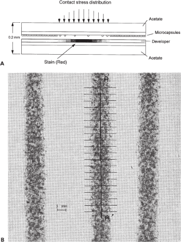 Figure 44.2. A: Functional schematic of PresSensor contact film, consisting of paired acetate layers, each approximately 0.1 mm thick. One layer is coated with reactant-filled microcapsules, and the other is coated with developer. When subjected to contact stress, some of the microcapsules rupture, liberating liquid reactant that turns red when it contacts the developer. The greater the contact stress, the greater the fraction of the microcapsules that rupture, and hence the denser the stain. B: Typical PresSensor patterns, magnified to show the discrete nature of the microstains resulting from individual microcapsule ruptures. Quantitation is usually by means of densitometry, and it is facilitated by digital image analysis. Here, an overlain coordinate axis (line A–A) is used to define a series of sampling profiles (transverse parallel lines). The three stains are from three repetitions of edge contact of a cylinder against a flat surface. Note that the staining pattern is reproducible on the global level, even though the distribution of microstains differs stochastically within each of the global stains. |
Unlike displacement measurements, the measurement of interfacial contact stress (e.g., the pressure across an interface such as an articular surface or a press-fit junction) poses
special difficulties for which no precision instrumentation is as yet commercially available. Any physical sensor inserted between the contacting surfaces necessarily disturbs the local contact configuration (7), often to the point of involving largely artifactual recordings. Special purpose techniques have been devised to circumvent this difficulty in select circumstances, such as retrorecessed transducers machined in the inner wall of a hollowed head of a femoral hemiprosthesis (8), or cartilage-isocompliant miniature load cells recessed in the articular surface of natural cadaver femoral heads (9). Most frequently, however, investigators have used thin pressure-sensitive sheets that span the entire contact surface. This approach, although in principle still disturbing the pre-existing contact pattern, at least avoids the major local stress redistributions occurring around discrete indwelling sensors.
special difficulties for which no precision instrumentation is as yet commercially available. Any physical sensor inserted between the contacting surfaces necessarily disturbs the local contact configuration (7), often to the point of involving largely artifactual recordings. Special purpose techniques have been devised to circumvent this difficulty in select circumstances, such as retrorecessed transducers machined in the inner wall of a hollowed head of a femoral hemiprosthesis (8), or cartilage-isocompliant miniature load cells recessed in the articular surface of natural cadaver femoral heads (9). Most frequently, however, investigators have used thin pressure-sensitive sheets that span the entire contact surface. This approach, although in principle still disturbing the pre-existing contact pattern, at least avoids the major local stress redistributions occurring around discrete indwelling sensors.
The two primary sheet-measurement approaches currently in use are pressure-sensitive film and multiplexed conductor arrays. Of the various pressure-sensitive films, the acetate product marketed by Fuji (under the trade name PresSensor) has become virtually synonymous with contact stress measurements in orthopedics. When subjected to pressure, the initially white acetate substrate stains red, the staining intensity correlating (nonlinearly) with pressure magnitude. Pressure transduction is achieved mechanochemically via rupture of reactant-containing microcapsules deposited on the film surface (Fig. 44.2). Quantitation is typically performed by means of digital image analysis (10). The film is limited to making static measurements, of modest accuracy (15% errors are typical), and it is subject to crinkling artifact over bicurvilinear surfaces (11). Nevertheless, the film is widely employed because it is inexpensive, easy to use, relatively thin (∼0.2 mm), and provides whole-surface mappings at a spatial resolution that is adequate for most purposes (12). Multiplexed conductor arrays such as those marketed by Tekscan (Fig. 44.3A) function by sampling either the electrical resistance or the electrical capacitance between alternative combinations of parallel conductor arrays situated in a row/column arrangement on opposite sides of a filler sheet (13). By means of electronic switching, the local pressure at individual conductor row/column intersections can be sampled rapidly enough (many thousands of times per second) to allow computational display of full-field transient pressure distributions in near real time, at frame rates in the range of 100 Hz (14). Although initially introduced for low-resolution applications such as foot–floor pressure, miniaturization of the conductor arrays has recently achieved sampling pixel sizes on the order of 0.7 mm2, thus inviting application to more demanding measurements such as contact stresses in articular joints. The principal disadvantages are that the technology is moderately expensive, that the conductor arrays are vulnerable to damage under harsh loading conditions, and that difficulties can arise in calibration because of nonlinearity and time dependency of the mechanoelectrical behavior of the filler sheets. Sensors of this type also need to be shaped for specific anatomic sites. Recently, versions configured to fit the human hip joint have been developed (Fig. 44.3B,C) (15). Salient performance characteristics for the above-described sensor modalities are summarized in Table 44.1.
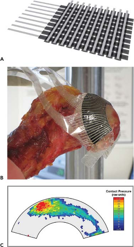 Figure 44.3. A: Schematic diagram of multiplexed conductor arrays used to measure transient contact stress. Piezoresistive filler material separates two orthogonal arrays of parallel conductors. To measure pressure at a specific junction, termed a “sensel,” the measurement circuitry samples the electrical resistance between the corresponding row and column of the respective conductor arrays. Because electronic switching permits very rapid scanning over many hundreds of such individual row–column combinations, two-dimensional contact stress distributions can be assembled computationally and displayed transiently. B: A multiplexed conductor sensor developed for the human hip, shown positioned on a cadaveric femoral head specimen. C: An instantaneous contact stress mapping for a human cadaveric hip, obtained using the sensor shown in Figure 44.3B. |
Materials Testing Machines
Materials testing machines (sometimes known as load frames), such as those marketed by MTS, Instron, AMTI, Bose, and others lie at the heart of most biomechanical setups used to make mechanical measurements on THA constructs
or materials. Two basic classes of machines are in common use: screw-driven and servohydraulic. Screw-driven machines use a precision gear drive to control rotational motions of two large and very stiff power screws, which in turn drive unidirectional motions of a massive transverse crosshead with which they mesh. Control circuitry allows the machine operator to program from a menu of input waveform choices (e.g., ramps, square waves), usually with the input being the imposed motion of the crosshead. Load developed in the specimen in response to the imposed displacement input is sensed by a load cell, normally user-mountable either on the traveling crosshead or on the fixed machine base. Advantages of screw-driven machines are their (relatively) low expense, and the fact that very large crosshead displacements are feasible, in principle spanning the full length of the power screws. Disadvantages are that maximum crosshead displacement speeds tend to be slow (on the order of a few centimeters per second), that it is difficult to precisely maintain/input specific load histories, and that torsional loading is feasible only with specialized additional fixturing.
or materials. Two basic classes of machines are in common use: screw-driven and servohydraulic. Screw-driven machines use a precision gear drive to control rotational motions of two large and very stiff power screws, which in turn drive unidirectional motions of a massive transverse crosshead with which they mesh. Control circuitry allows the machine operator to program from a menu of input waveform choices (e.g., ramps, square waves), usually with the input being the imposed motion of the crosshead. Load developed in the specimen in response to the imposed displacement input is sensed by a load cell, normally user-mountable either on the traveling crosshead or on the fixed machine base. Advantages of screw-driven machines are their (relatively) low expense, and the fact that very large crosshead displacements are feasible, in principle spanning the full length of the power screws. Disadvantages are that maximum crosshead displacement speeds tend to be slow (on the order of a few centimeters per second), that it is difficult to precisely maintain/input specific load histories, and that torsional loading is feasible only with specialized additional fixturing.
Table 44.1 Characteristics of Common THA Biomechanical Sensors | |||||||||||||||||||||||||||||||||||||||||||||||||||||||||||||||||||||||
|---|---|---|---|---|---|---|---|---|---|---|---|---|---|---|---|---|---|---|---|---|---|---|---|---|---|---|---|---|---|---|---|---|---|---|---|---|---|---|---|---|---|---|---|---|---|---|---|---|---|---|---|---|---|---|---|---|---|---|---|---|---|---|---|---|---|---|---|---|---|---|---|
|


