Fig. 9.1
Surgeons feedback presented on a small LCD touch screen mounted onboard the hand held tool
Planning Surgery
Being currently (CT) image based, SOS provides fully integrated software tools and interfaces in one application to reconstruct three-dimensional models from raw data of Dicom CT studies (Fig. 9.2).
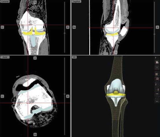
Fig. 9.2
Planning based on CT (SOS screen capture)
Once the patient specific bone models are created by SOS, the graphical user interface provides tools for the user to define anatomical landmarks, and to choose an implant from a database with multiple implant brands, models and sizes, including design characteristics and 3 dimensional implant models originating from manufacturer computer aided design (CAD) data. The surgical plan can be based on any of the conventional TKR alignment techniques based on the mechanical axis and joint line, and rotationally based on the Epicondylar axis [21], or Posterior condyle alignment, or Whiteside’s Line [22] (Fig. 9.3). Moreover, the user can fine-tune the plan by freely moving the tibial and femoral TKR component models on the screen relative to the bones. This allows the user to optimize other parameters such as articular surface matching/coverage, and to avoid notching or overhand of the femoral component say.
Fig. 9.3
Alignment: (a) Epicondyle axis; (b) Posterior condyles; (c) Whiteside line (SOS screen capture)
Navigated Power Tools
SOS uses a commercial tracker (NDI Polaris Spectra) and custom tibial and femoral reference frames to navigate the bones. However, unlike a conventional navigated jig system, SOS also directly tracks the powered cutting instruments in 3D via reference frames. After a quick registration process, the system is able to sense the location of both the bones and instruments relative to their reference frames, and therefore SOS can track the location of the bones and instruments in real time, indicating to the user how and where to cut. Customized wireless electronics embedded in the power tools allows SOS to slow down and/or stop the cutting/drilling if the user deviates from the surgical plan, which prevents the bone from being cut improperly. The surgeon can optionally empower this functionality, and adjust the cutting accuracy envelopes they allow themselves in each degree of freedom separately (Fig. 9.4).
Fig. 9.4
Navigated power tools
Simplified 2D Guidance
In addition to the dynamic 3D virtual environment, SOS also provides a simplified (and more condensed) 2D guidance component. Inspired by flight simulators, the 2D guidance component displays a horizon line representing the plane of the cut, as well as lines representing the tip and back of the blade (see Fig. 9.5): When all three components coincide, it means that the potential bone cut is correct (tool is aligned properly with the cut), so that the user can proceed with the cutting. Similar guidance is shown for reciprocating saw (with vertical as opposed to horizontal lines) and drill (with cross-wired bulls-eye like target instead of lines).
Fig. 9.5
Real time feedback for surgical guidance: (a) Full 3D guidance view for the oscillating saw; (b) 2D guidance for Oscillating saw; (c) Sample of 2D guidance for Reciprocating saw; (d) Sample of 2D guidance for Drill
Smart Views
During a procedure, the surgeon may prefer to see a particular perspective of the virtual environment (3D view), based on a certain combination of orientations of the patient model and the instrument. For example when aligning the oscillating saw to make the anterior cut for a femoral component, the user would favor a lateral view of the bone so the guidance planes would appear like straight lines (see Fig. 9.5). This would be preferred by most users compared to a distal or anterior view, where the model of the saw would obstruct the view of the bone and the planar cut guidance plane. Although surgeons may desire to have control over the view, they normally do not want to be encumbered by manipulating system controls or interacting with any computer during a procedure.
Therefore, the SOS system is optionally configured to sense the context and the intended cut of the surgeon by real-time computations of the handheld tool motions and approach and proximity to a certain cut. The system then automatically and dynamically changes the graphical environment view (perspective angle) to the most suitable default or relevant perspective view of the surgical scene previously chosen by the surgeon. The system naturally allows the surgeon to manually select any view/perspective the surgeon may desire. However, anticipating what the surgeon is about to do based on the relative position and orientation of instruments and bones contributes to a user adaptable/configurable knowledge based system.
Experimental Case Studies
Different versions of the system described above have been built and bench tested to evaluate feasibility of the concept and assess usability and accuracy. Two of the most comprehensive studies are cited here and summarized here:
Study 1: Navigated Freehand Cutting Experiments with Seven Independent Surgeons [23]
For this study, seven independent orthopaedic surgeons at different stages of their career have participated in testing. A distal femur was simulated on a surgical table by identical replicas molded from synthetic material of similar cutting-feel as real bone. An early elementary prototype version of the system described above was used to navigate the bone specimen and an oscillating bone saw fitted with passive reference frames. It was programmed with the ideal locations of the five distal femur plateau cuts for a widely used TKR system. Each surgeon performed five timed experiments in a 1-day session (Fig. 9.6).
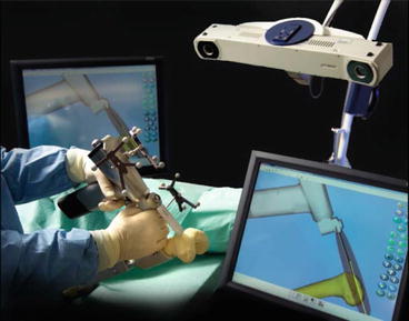
Fig. 9.6
Navigated Freehand Cutting system, early elementary prototype used on Study1
The surgeons varied in speed but showed a steep learning curve, with 10.2 ± 4.3 min average cutting time (see Fig. 9.7). This was even faster than measured in our previous studies [24], which were in-turn faster than with conventional instruments, promising savings in surgeon and OR tourniquet times. From the thousands of digitized surface points on each cut-surface, the average overall average surface roughness Ra was 0.19 mm, and the average difference between the highest-50-peaks and lowest-50-valleys was <1.2 mm. These also confirmed previous measures, that the cut surface smoothness was reproducible and adequate, especially for cemented cases.
Fig. 9.7
A graph shows times of bone cutting for all surgeons, broken down and averaged according to the order in which the bones were cut. Values are expressed as mean and SD
Although tightness of how the implant fitted the bone prior to cementation was not targeted for this cemented implant, 21 out of 35 bones were tight on the implant-trial, and others slightly loose (without cementation). The worst looseness was in the implant “flexional” sense with average <1.6°, and <1 mm in translation. Average implant alignment error was 1.2°, and always <4.7° sagittally, <3.6° frontally and <2° axially. Linear-translation errors averaged 1.4 mm, and <4.2 mm everywhere, with some systematic undercutting of the distal plateau evident, attributed to surgeon being conservative and not following the computer guidance all the way for fear of overcutting. Digitization and 3D analysis of all cut-surfaces echoed the above results, showing the extreme-outliers to be the chamfers which were deliberately treated as less important and therefore were less intricately cut by most surgeons (Fig. 9.8).
 Virtual Preoperative Planning
 Computational Image-Guided Technologies in Cranio-Maxillofacial Soft Tissue Planning and Simulation
 Patient-Specific Instruments in Orthopedics
 Virtual Cranio-Maxillofacial Surgery Planning with Stereo Graphics and Haptics
 Navigation in Spinal Surgery
 3D Projection-Based Navigation


Related posts:
Virtual Preoperative Planning
Computational Image-Guided Technologies in Cranio-Maxillofacial Soft Tissue Planning and Simulation
Patient-Specific Instruments in Orthopedics
Virtual Cranio-Maxillofacial Surgery Planning with Stereo Graphics and Haptics
Navigation in Spinal Surgery
3D Projection-Based Navigation
Stay updated, free articles. Join our Telegram channel
Full access? Get Clinical Tree
