CHAPTER 12 Diagnostic imaging
Plain radiographs
Generation of radiographs
Conventional radiographs
Conventional X-rays are generated by the passage of a high voltage through a heated coiled tungsten wire (the cathode) in a toughened glass tube containing a vacuum, producing free electrons in a process known as thermionic emission. At the other end of the tube is the anode, consisting of a heavy metal disc, usually tungsten, embedded in a copper bar, which rotates to absorb heat. When a high potential difference is applied between the electrodes, the electrons from the cathode stream at high velocity towards the anode and bombard the tungsten target. If a positive nucleus of a target atom is bombarded by fast-moving free, negatively charged electrons from another source, a repulsion and braking effect (the bremsstrahlung process) takes place. The electrons decelerate and emit energy in the form of radiation and if the energy levels are high enough, the radiation is in the form of X-rays.
When an X-ray beam passes through tissues, such as the foot, and strikes a sensitive film emulsion, it produces a chemical change and forms a negative image of the tissues, which may be viewed once the film has been processed. Tissues that lie in the path of the X-ray beam absorb or attenuate X-rays to differing degrees. Dense tissues that result in most X-ray absorption such as bone or calcium produce a white shadow on the X-ray and this area of increased density is known as increased radiopacity. Tissues that result in least X-ray absorption such as air produce a black shadow on the X-ray and this area of decreased density is called increased radiolucency. These differences account for the radiographic image (Table 12.1).
Table 12.1 Attenuation of the X-ray beam
| X-ray attenuation | Tissue | Effect on radiograph |
|---|---|---|
 | Air or gas | Black image |
| Fat | Dark grey image | |
| Soft tissue | Grey image | |
| Bone or calcium | White image |
Digital radiographs
• Digital radiography. Digital radiographs are obtained using new digital X-ray machines usually with large flat panel detectors that allow efficient conversion of X-rays directly into a digital signal with rapid production of images. This usually requires that the entire existing X-ray room is replaced with expensive digital acquisition devices.
• Computed radiography. Computed radiography uses standard X-ray machines so there is no need to change existing machines as is required with digital radiology. Only the recording device requires a change. In computed radiography, the image is exposed on a phosphor plate rather than a film. The phosphor plates, like film, are stored in cassette format. As X-rays pass through the patient, the phosphors absorb and store X-ray energy. This trapped energy comprises a latent image. The exposed cassette is transferred to a computed radiography unit which extracts and digitises the information stored in the plate to produce a digital image. The image is then transferred to a reader where it is displayed on a monitor. The digital image can be modified to adjust the exposure, which reduces the number of image retakes. Once the quality is approved, the image is usually stored in a digital format and viewed on a work station, although the image may be printed on film in a laser camera if required.
Digital images have many advantages over conventional radiographs. Digital images are of better quality and may be manipulated using a variety of image processing capabilities while being viewed at a workstation. This includes image contrast and brightness optimisation by manipulation of window width and level settings, magnifying, measuring and labelling certain structures. PACS allows multiple copies of the same image to be viewed simultaneously at different locations by a range of practitioners allowing discussion over diagnoses. The clinical history associated with the imaging examination and final report may be viewed in conjunction with the images. PACS systems may be integrated into the electronic patient record (EPR) which allows access to all patient details including clinical information and laboratory results. Image storage and retrieval is more efficient as all patients’ previous radiographs are immediately available whenever their record is accessed thus preventing lost radiographs and the need to search for old films. Transmission of radiographic images is greatly facilitated allowing images to be sent electronically to other institutions for advice or patient referral. Although PACS inevitably results in increased IT support costs, expensive film and costs associated with film storage and handling are significantly reduced.
Radiographic views
Dorsiplantar view
Anatomical review areas
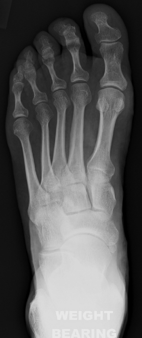
This general purpose view shows the majority of the foot from the midtarsal area distally (Fig. 12.1). The neck of the talus, the distal edge of the calcaneum, the tarsus, metatarsals and phalanges are clearly seen. The calcaneocuboid and talonavicular joints which make up the midtarsal (Chopart) joint are visualised as are the tarsometatarsal (Lisfranc) joints. The sesamoid bones are seen through the head of the first metatarsal. Usually the bodies of the talus and the calcaneum are occluded by superimposition of the lower ends of the tibia and fibula.
Dorsiplantar oblique view
Anatomical review areas
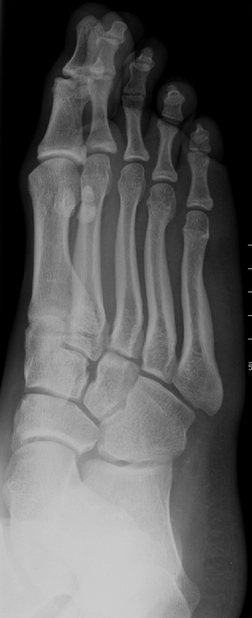
This view gives a distorted image of the midtarsal area, but is particularly useful for the open view given of the articular facets in the area, particularly the talonavicular, navicular-cuneiform and calcaneocuboid joints (Fig. 12.2). It should be possible to see the outlines of the cuneiforms, but it can be difficult to see the facets of all the intercuneiform joints due to superimposition. The anterior aspect of the subtalar joint and the tarsometatarsal joints are also well seen. Good views of the distal calcaneus, metatarsals and phalanges are obtained.
Lateral view (weightbearing)
Anatomical review areas
This view shows the tibial and fibular malleoli superimposed over the trochlear surface of the talus which should be domed and smooth in outline. The posterior lip of the tibia, also known as the posterior or third malleolus, is best seen on this projection. The facets of the subtalar joint and the calcaneus are well seen as are the calcaneocuboid and talonavicular joints. The sustentaculum tali and sinus tarsi are usually apparent. The midtarsal complex is partially obscured by the multiple superimpositions of the cuneiforms and metatarso-cuneiform articulations, although the first metatarso-cuneiform joint is usually well seen. Just proximal to this joint is the second and third metatarso-cuneiform joints which can be visualised with some superimpositions. The lesser metatarsals are partially superimposed over each other, although the first metatarsal, hallux, and first metatarsophalangeal joint should be easily distinguishable (Fig. 12.3).

Anteroposterior ankle
Anatomical review areas
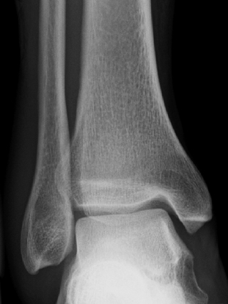
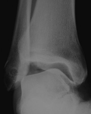
The ankle mortise including the trochlear surface of the talus and the articulations with the tibial plafond and malleoli are well seen with this view (Fig. 12.4). It is useful if ankle injury is suspected and avulsion fractures, which occur with inversion and eversion injuries, can usually be seen on this view. Virtually no detail of the forefoot is seen due to marked superimposition.
This view is sometimes taken as a non-weightbearing stress radiograph in which the foot is held in inversion or eversion and the amount of ligamentous damage is checked by assessing the degree of tilt of the talus within the joint (Fig. 12.5). This may be a painful procedure and the patient may require local anaesthesia.
Axial sesamoid view
Anatomical review areas
Although not commonly standard, this view clearly demarcates the sesamoids which should be smooth in outline and positioned under the head of the first metatarsal on either side of the intersesamoidal ridge. The ends of the lesser metatarsals are also seen and may determine whether a long or plantarflexed metatarsal disturbs foot dynamics (Fig. 12.6).
Basic radiographic assessment
A vast amount of information can be gleaned from a plain radiograph. The ABCS system of radiological assessment may be useful, where:
Alignment
Dorsiplantar view
Commencing at the hindfoot, the longitudinal axis of the hindfoot is a line parallel to the distal portion of the lateral border of the calcaneus. In the normal foot, it is parallel to the long axis of the fourth metatarsal (Fig. 12.7). The talocalcaneal angle is measured between the longitudinal axis of the hindfoot and a line along the midline axis of the talus (Fig. 12.7). There is usually a 15–35° more lateral axis of the calcaneus compared with the talus. A smaller angle means that the calcaneus is directed closer to the midline and there is hindfoot varus or supination with increased superimposition of the talus on the calcaneus. A larger angle means that the calcaneus is directed further from the midline and there is hindfoot valgus or pronation.
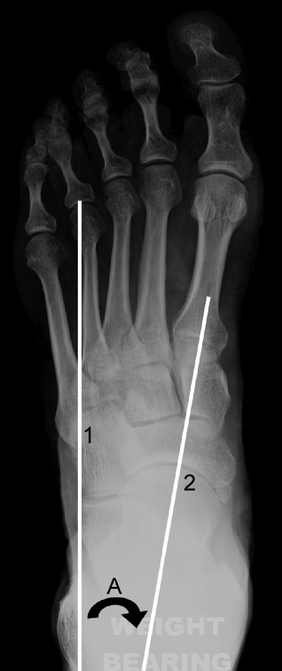
Forefoot varus and valgus is often discussed as a relationship between the talus and the first metatarsal, even though these bones are not truly adjacent. Simply put, the midline axis of the talus normally goes through the base of the first metatarsal (Fig. 12.7). If the axis of the talus lies lateral to the first metatarsal, the metatarsal is directed closer to the midline and there is forefoot varus or supination (also referred to as inversion). The bases of the metatarsals tend to converge more than normal and the proximal metatarsals are superimposed. If the axis of the talus lies medial to the first metatarsal, the metatarsal is directed further from the midline and there is forefoot valgus or pronation (also referred to as eversion). The metatarsals are less convergent than normal, more parallel with less overlap.
The longitudinal axis of the lesser tarsus is perpendicular to a line that transects the lesser tarsus which extends across the tarsus from halfway between the medial aspect of the talonavicular joint and the medial aspect of the first tarsometatarsal joint to halfway between the lateral aspect of the calcaneocuboid joint and the lateral aspect of the fifth tarsometatarsal joint (Fig. 12.8).
Normally, 75% of the head of the talus articulates with the navicular. In a pronated foot the head of the talus moves out of alignment with the cupped surface of the navicular and there is progressive abduction of the lesser tarsus. The lesser tarsus abduction angle is the angle between the longitudinal axis of the lesser tarsus and the longitudinal axis of the hindfoot (Fig. 12.8). This angle increases with pronation and decreases with supination. The talonavicular angle is between the midline axis of the talus and the bisection of the lesser tarsus (normal 60–80°) (Fig. 12.8). This angle is greater than 80° in the supinated foot and less than 60° in the pronated foot.
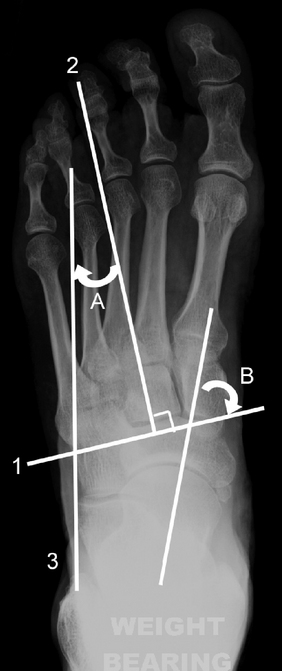
The longitudinal axis of the metatarsus is a longitudinal bisection of the second metatarsal (Fig. 12.9). The metatarsus adduction angle is the angle between the longitudinal axis of the metatarsus and the longitudinal axis of the lesser tarsus (normal <15°) (Fig. 12.9). A higher figure indicates that metatarsus adductus or deviation of the forefoot to the midline is present. Severe metatarsus adductus is associated with hindfoot valgus. The metatarsus primus adductus angle, also known as the metatarsus primus varus or first intermetatarsal angle, by strict definition refers to a varus relationship of the first metatarsal with respect to the medial cuneiform. In everyday practice, metatarsus primus adductus is measured by considering the angle between longitudinal bisections of the first and second metatarsals (it is assumed that the second metatarsal axis gives a reasonable approximation of the medial cuneiform axis) (Fig. 12.9). An angle of more than 10° is considered abnormal and is associated with hallux valgus.
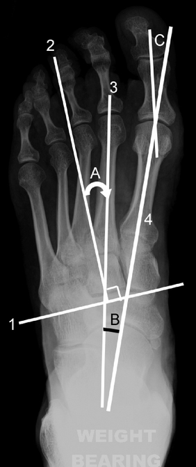
In hallux valgus, the proximal phalanx of the great toe (hallux) is directed further from the midline with respect to the first metatarsal. If a longitudinal bisection of the first proximal phalanx is compared with a longitudinal bisection of the first metatarsal, the hallux valgus angle can be measured (Fig. 12.9). The hallux may normally deviate laterally by a small amount and an angle of less than 15° is generally considered acceptable. Hallux valgus is mild with an angle of 16–25°, moderate with an angle of 26–35° and severe with an angle of greater than 35°. The common term for hallux valgus is ‘bunion’ from which the term ‘bunionette’ (also known as tailor’s bunion) is derived. This describes a prominence lateral to the fifth metatarsal head secondary to a varus angulation of the fifth proximal phalanx with respect to the fifth metatarsal.
Lateral view
The calcaneal inclination axis is a line along the inferior surface of the calcaneus connecting the most inferior point of the calcaneal tuberosity with the most distal inferior point of the calcaneus at the calcaneocuboid joint (Fig. 12.10). The calcaneal inclination angle is between the calcaneal inclination axis and the supporting surface and reflects the height of the foot framework (Fig. 12.10). Measurements of 10–20° would be considered low, 20–30° medium and >30° high. The measured angle varies according to whether the foot is abnormally pronated or supinated and clinical judgement is important.
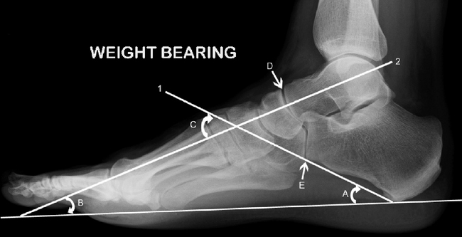
The talar declination angle is the angle between a bisection through the body and neck of the talus and the supporting surface (normal approximately 21°) (Fig. 12.10). A continuation of the midline talar axis should bisect the first metatarsal shaft. If the first metatarsal axis extends downwards compared with the talar axis, i.e. the first metatarsal is steeper in relation to the horizontal, the talar declination angle decreases and the line falls above the first metatarsal. This indicates that the longitudinal arch is high and there is a cavus foot (pes cavus). Conversely, if the talar axis extends downwards compared with the first metatarsal axis, the talar declination angle increases and the line falls below the first metatarsal. This is indicative of a low to flat longitudinal foot arch or a planus foot (pes planus).
Another method for assessing cavus or planus is measuring the angle of the longitudinal arch between the calcaneal inclination axis and a line which extends along the undersurface of the fifth metatarsal (normal 150–170°). Cavus is present with an angle of less than 150°. In planus the angle is increased approaching 180°. The lateral talocalcaneal angle is between the calcaneal inclination axis and the midline axis of the talus (normal 35–50°) (Fig. 12.10). Boehler’s angle is measured between a line drawn along the superior margin of the subtalar joint and a line drawn along the posterior superior border of the calcaneus (normal 20–40°).
The talonavicular and calcaneocuboid joints together produce a superimposition on a lateral X-ray known as the cyma line (Fig. 12.10). These curved joints together form a reverse ‘lazy S’ as an intact curve in a normal foot. In a pronated foot the ‘S’ becomes broken as the talonavicular joint moves anterior and plantar to the calcaneocuboid joint and the reverse occurs in a supinated foot.
Anatomical variation
Hallux sesamoids
The medial and lateral sesamoids should appear as two smooth ovoid structures approximately 0.5 cm proximal to the articular surface of the first metatarsal head. Sesamoids may be symptomatic for several reasons: fractures, osteonecrosis, inflammation (sesamoiditis), infection and involvement in degenerative or inflammatory joint disease (Fig. 12.11). In a case of developing hallux valgus, the sesamoids progressively move laterally, eventually ending up in the interspace between the first and second metatarsals. Sesamoids may be bipartite or multipartite and occur under any of the other metatarsophalangeal or interphalangeal joints.
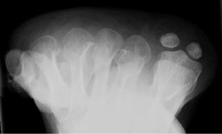
Polydactyly is the presence of additional phalanges or complete digits (Fig. 12.12). Brachydactyly is due to partial failure of development of a metatarsal or phalangeal segment leading to shortening of the digit. Congenital aplasia is complete failure of development of a segment and is rare (Fig. 12.13).
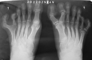
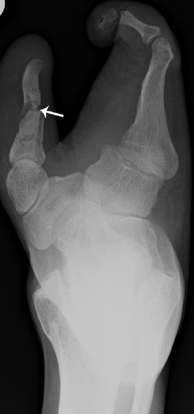
Figure 12.13 Congenital aplasia. Dorsiplantar radiograph. Congenital aplasia with a fracture of the medial digit (arrow).
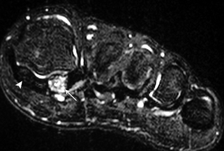
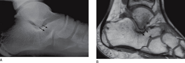
Tarsal coalitions may be fibrous (syndesmosis), cartilaginous (synchondrosis) or osseous (synostosis) and are thought to represent failure of proper segmentation of the tarsal bones. Coalitions occur in about 6% of the population, may be bilateral and result in restricted subtalar joint motion. The more common forms are calcaneo-navicular and talocalcaneal, which usually occurs at the middle facet of the subtalar joint. Calcaneo-navicular coalition is usually well seen on oblique views (Fig. 12.14A). Talocalcaneal coalition may be associated with a prominent talar beak arising from the dorsal aspect of the head or neck of the talus. Suspected tarsal coalitions may be confirmed with CT or MRI (Fig 12.14B). Limited subtalar joint motion results in increased stresses elsewhere in the tarsus and this may result in bone marrow oedema adjacent to the coalition on MR images.
Bone density
Osteoporosis
• dual energy X-ray absorptiometry (DEXA) – used on the spine and femoral neck
• single-photon or dual-photon absorptiometry (SPA or DPA) – measures bone density in the forearm
• quantitative computed tomography (QCT) – used on the spine
• ultrasound – may be used to indicate the bone density of the calcaneum.
Osteomalacia
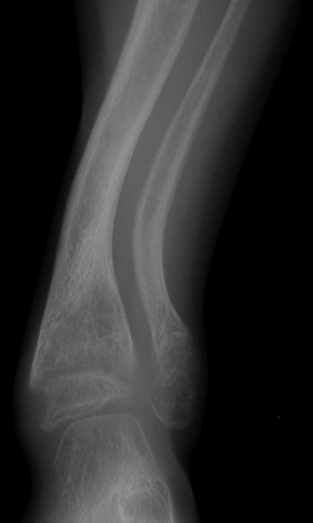
In osteomalacia, there is a failure of the osteoid tissue to mineralise. The commonest causes of osteomalacia are renal osteodystrophy and disorders of vitamin D metabolism. A distinctive radiographic feature is Looser’s zones, which are areas of unmineralised osteoid that may develop insufficiency fractures, and tend to occur in the pelvis and scapula. The trabecular pattern is often coarse and indistinct. Osteomalacia in children is called rickets. Rickets causes characteristic enlarged and irregular epiphyseal plates with splayed metaphyses and bowing of the bones from bone softening (Fig. 12.15). As in adults, the commonest cause is renal disease, although other causes such as biliary disease and dietary insufficiencies are seen.
Osteosclerosis
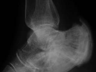
Paget’s disease is a common disorder of unknown origin which can involve the entire skeleton or isolated bones, including the bones of the feet. The disease causes excessive bone resorption followed by haphazard new bone formation and remodelling. The bones are enlarged and appear dense with a coarse trabecular pattern and thickened cortex (Fig. 12.16). Although the bones are enlarged and appear dense on X-ray they are of poor quality and microfractures are common. Paget’s disease predisposes to an increased incidence of sarcoma, although less than 1% progress to malignancy.
Metastatic bone disease with diffuse sclerotic deposits may rarely mimic osteosclerosis. Primary tumours are usually carcinoma of the breast and prostate. Radiolucent components of the metastasis and cortical destruction may be present.

Stay updated, free articles. Join our Telegram channel

Full access? Get Clinical Tree


