, Paul D. Siney1 and Patricia A. Fleming1
(1)
The John Charnley Research Institute Wrightington Hospital, Wigan, Lancashire, UK
There is little doubt that the dramatic occurrence of early post-operative dislocation undermines patient’s confidence and disappoints the surgeon. Much has been written on the subject, many attempts have been made to analyse the factors involved and offer practical solutions. Most have focused on two aspects: diameter of the head of the femoral component and the orientation of the components in order to achieve the greatest range of movements with a minimum chance of neck-cup rim impingement.
It may, therefore, be of interest to consider some aspects of component design, range of movements, impingement and dislocation.
Hip Joint Movement
Movement, in space, can take place in three or a combination of the three planes. In a ball and socket articulation the range of movement is independent of the diameter of the ball. The movement in the natural hip joint is restricted to two planes; separation of articular surfaces does not occur naturally. The functional range is a combination of movement in two planes – rotation on the femoral neck is the combining motion. The range of rotation is independent of both the diameter of the head and the head-neck diameter ratio. Rotation shortens the hip capsule and resists separation of the joint spaces. In a design of any total hip arthroplasty the limit to the arc of movement is set by the contact of the neck of the stem with the rim of the cup.
Head-Neck Diameter Ratio and Arc of Movement
In a design with a hemispherical cup, without a chamfer, a fully spherical head and a neck of uniform diameter, the possible arc of movement, is proportional to the head–neck diameter (radius) ratio (Fig. 19.1).
Fig. 19.1
Head-neck diameter ratio and arc of movement. One half of the arc of movement (θ) in a hemispherical cup: also referred to as “angle to impingement” – of the neck of the stem on the rim of the cup
The arc of movement is given by the formula:-
θ = cos – 1(r/R) arc of movement
r = neck radius
R = head radius
∴ Full range of movement in a plane is θ × 2.
The arc of movement for head-neck diameter ratios up to 5:1 is given in Table 19.1 and Fig. 19.2. The relationship is not linear; when comparing ratios the resulting scale is logarithmic. Increasing the head diameter and, therefore, the head-neck ratio beyond 2.2:1 offers only moderate increase in the arc of movement.
Table 19.1
Head-neck diameter ratio and the possible arc of movement (10 mm diameter neck taken as probably the lowest limit acceptable)
Head – neck ratio | Range of movement (degrees) |
|---|---|
1:1 | 0.0 |
1:2 | 67.1 |
1:4 | 88.8 natural hip |
1:6 | 102.6 |
1:8 | 112.5 |
2:1 | 120.0 |
2:2 | 125.9 Charnley LFA |
2:4 | 130.8 |
2:6 | 134.8 |
2:8 | 138.2 |
3:1 | 141.1 |
3:2 | 143.6 |
3:4 | 145.8 |
3:6 | 147.7 |
3:8 | 149.5 |
4:1 | 151.0 |
4:2 | 152.5 |
4:4 | 153.7 |
4:6 | 154.9 |
4:8 | 156.0 |
5:1 | 156.9 |
Fig. 19.2
Arc of movement, in a ball and socket articulation as an expression of head-neck diameter ratio. (Natural hip has a ratio of 1.4 degrees, Charnley hip has a ratio of 2.2 degrees)
Impingement
With the neck of the stem in a central position, with respect to the cup, impingement will occur at one half of the possible arc of movement and may be conveniently called “the angle to impingement”. At that stage the summit of the head will be an arc’s distance (the arc based on the radius of the head) away from the cup rim (Fig. 19.3). Movement past impingement will bring the summit of the head to the rim of the cup reaching “the limit of stability” Movement past the limit of stability will result in dislocation.
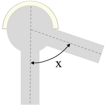
Fig. 19.3
Angle to impingement and limit of stability. Summit of the head will be an arc’s distance away from the cup rim
Increasing the Arc of Movements, Putting Off Impingement
There are four possible ways of achieving this objective.
Increasing Head Diameter
Conceptually attractive; in practice the limit is set by the size of the acetabular cavity. Increasing the diameter beyond a certain limit demands the use of hard on hard articulations and a departure from the clinically proven concept of low-frictional torque as well as the clinical experience with the materials: ultra high molecular weight polyethylene/metal/alumina ceramic.
Increasing head diameter may reduce the effective neck length. If the neck length is maintained then the offset would be increased. Reducing the thickness of the cup wall diminishes the usefulness of a chamfer.
Reducing Neck Diameter
A simple practical option; it increases the angle to impingement in proportion with the head-neck diameter (radius) ratio but reduces the angle to the limit of stability by the same degree.
Furthermore, since the strength of the neck is related to the cross-section area, reducing the neck diameter reduces its strength in the proportion of square of the radius. The material used becomes the limiting factor. In any symmetrical design, as outlined here, there is no direct, straight line relationship, between the neck-head ratio and the possible arc of movement (Fig. 19.1) – the relationship is logarithmic (Fig. 19.2). This cannot be considered in hip resurfacing procedures.
Fashioning a Chamfer
A chamfer is produced by bevelling the edge of the rim of the cup. For ease of manufacture, inventory and surgical technique, the chamfer is usually circumferentially symmetrical. Fashioning the chamfer increases the angle to impingement but reduces the angle from impingement to the limit of stability by the same degree (Fig. 19.4). Since functional range of movement of the hip joint is primarily anterior to the coronal plane, the chamfer need only be fashioned anteriorly. The examples that follow this principle are the long posterior wall cup of Charnley and the angle-bore cup.
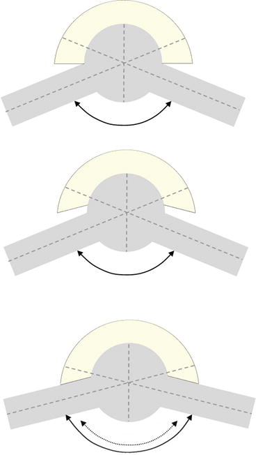
Fig. 19.4
Chamfer on cup. Fashioning the chamfer increases the angle to impingement but reduces the angle from impingement to the limit of stability by the same degree
Related posts:


Stay updated, free articles. Join our Telegram channel

Full access? Get Clinical Tree


