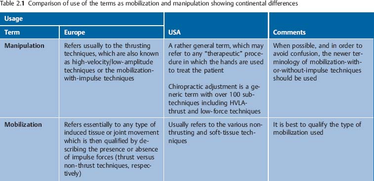
2 Definitions and Principles of Manual Medicine Diagnosis and Treatment Following the Fischingen Conference in Switzerland (Dvořák et al., 1984) the following clinical definitions have been utilized in the international community during the past 20 years (Dvořák et al., 2004). In general, a distinction is made between manipulation and mobilization techniques. Manipulative techniques typically employ a thrusting type of maneuver, known as the classical “manipulation”; techniques that do not use this maneuver are categorized as mobilization techniques. In the United States, manipulation refers to any therapeutic procedure in which the hands are used to treat the patient. It is therefore a rather general term in this usage. In Europe, manipulation refers to what is described in English or according to American osteopathic terminology as “high-velocity, low-amplitude thrust” (HVLA). Spinal manipulation or spinal manipulative treatment refers to specific manual medicine maneuvers or special hand “applications” directed at the spine. This term that has commonly been used in the literature to reflect the “high-velocity, low-amplitude” type of maneuvers applied to the spine. “Mobilization” is described in the United States as a soft-tissue and articulatory type of treatment, and includes other techniques such as myofascial release and muscle energy. In Europe, this term refers to articular mobilization in the absence of thrusting forces. Both of these terms describe the same entity, with “thrust” being preferred in the English language, and “impulse” being more common in the European schools. In this text, the terms mobilization-with-impulse and mobilization-without-impulse are employed, and the individual treatment techniques are described as manipulative or mobilizing procedures, respectively (Dvořák et al., 1984) (Table 2.1). A summary overview of some of the most commonly used manual therapy techniques is given in Table 2.2 (after Dvořák et al., 2004, with permission). The physiologic motion during both active and passive movement in a synovial joint, e. g., the facet or apophyseal joint or the joints of the limbs, is a combination of rolling and gliding motions. The architectural shape of the individual joint, along with its associated ligaments and muscles, determines the direction and extent of this roll-and-glide motion (Fig. 2.1). Motion can be described by using a three-dimensional coordinate system with three primary axes, about which rotation takes place. These axes may be designated the x-, y-, and z-axes. In this system, the x-axis projects laterally, the y-axis projects vertically, and the z-axis projects frontally. See Table 2.3
Definitions and General Principles
Manipulation and Mobilization Treatment Techniques
Manipulation
Mobilization
Thrust or Impulse Techniques
Further Definitions and Principles of Manual Medicine
Angular Motion
| Primary Axis of Rotation | Primary Plane of Motion |
Flexion and extension | = rotation around the x-axis | Sagittal plane |
Inclination (flexion at C0 to C2) | = rotation around the x-axis | Sagittal plane |
Reclination (extension at C0 to C2) | = rotation around the x-axis | Sagittal plane |
Axial rotation | = rotation around the y-axis | Transverse plane |
Side-bending | = rotation around the z-axis | Frontal or coronal plane |
Abduction, adduction | = rotation around the z-axis | Frontal or coronal plane |
Elevation, depression | = rotation around the z-axis | Frontal or coronal plane |
Fig. 2.1 Roll and glide motions.
+y = Traction
−y = Compression
+x, −x = Lateral gliding
+z, −z = Anteroposterior gliding
A ⇒ A1 = Gliding
+y ⇒ y1 = øx= Rotation about x-axis
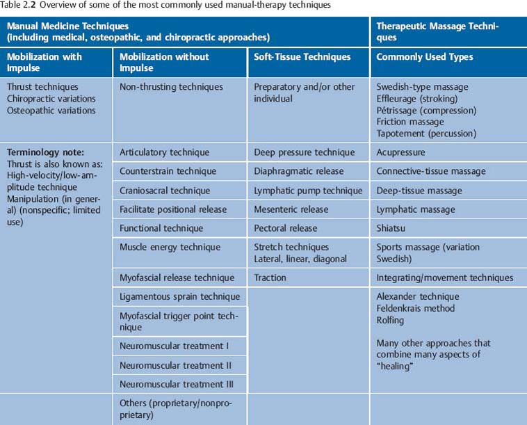
Fig. 2.2 Coefficient of friction.
Starting position: The coefficient of friction (R) is increased when there are degenerative changes in the articular cartilage surface.
Phase 1: Onset of angular joint motion. Initially there is a pure rolling motion as the friction resistance is comparatively high.
Phase 2: Continued angular motion beyond Phase 1 will be less smooth and will often become quite jerky, while the tension in the tendons overcomes the friction resistance.
The rolling characteristics of a synovial joint are determined by a number of variables that influence the joint’s internal coefficient of friction. These include the joint’s particular geometrical shape and articular surface and also the mechanical properties of the associated bone, cartilage, ligaments, tendons, muscles, synovial fluid, and other relevant soft tissues.
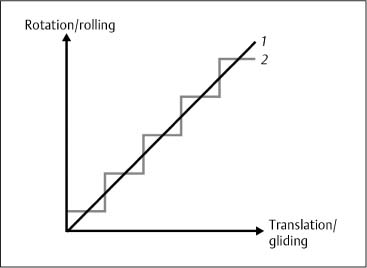
Fig. 2.3 Joint crepitus
1: Roll-gliding behavior in a “smooth,” unaffected “normal” joint.
2: Roll-gliding behavior when the joint is affected by degenerative processes.
The level of the internal coefficient of friction is directly related to the extent of internal resistance to motion. As long as the coefficient of friction is held at a minimum, the internal resistance is low. Friction can dramatically increase as a function of progressive arthritic degenerative changes that affect the internal structure of the joint. In the extreme, this is most evident when there is bone-on-bone contact where the coefficient of friction will have risen to a level at which very little joint motion, if any, is possible (Fig. 2.2). A change in the internal coefficient of friction from a normal, healthy state will be associated with a discontinuous roll-and-glide pattern of motion (Fig. 2.3). Mechanically, this will negatively affect the soft tissues associated with the affected joint, as they have to perform “increased work,” due to the uneven and discontinuous motions to which they are subjected.
Translatory Motion
All of the synovial joints, including the apophyseal or facet joints in the spine and the peripheral joints, allow passive translatory motion. Translatory motion takes place in a linear fashion, along the axes of rotation.
The extent of translatory motion has a direct relationship with angular mobility. A decrease in angular motion is always associated with diminished translatory movement and vice versa (Fig. 2.4).
Joint Play
Joint play is the sum of all possible passive, angular, and translatory motions within the neutral zone. The clinical examination of joint play requires good tactile and palpatory skill.
Mechanical Properties of the Elastic Structures Related to the Joints and Spinal Segments
The motion characteristics of the synovial joints in the limbs and at the facets are demonstrated conceptually in Figures 2.5 and 2.6 in response to different loading forces and induced or available motion. These curves represent the relationship between and effects of the various mechanical forces as a result of the interplay between factors such as a joint’s architecture, ligaments, joint capsule, and the presence of internal joint friction, among others. These concepts originate from a mechanical-engineering perspective in experimental studies using cadavers. Therefore there are several caveats.
First, the long-term effects of active muscular contraction on joint motion have not so far been fully elucidated. Secondly, work still needs to be done on the reaction in and effects on biological materials as a result of the rate of loading. Such considerations, at least in theory, are thought to explain the potential differences in effect between the rapid high-velocity, low-amplitude impulsive techniques and the more slowly performed muscle energy techniques, for instance. Third, it is important to remember that the mechanical function of biological tissues depends on physical and chemical properties, which in turn are an expression of their molecular composition and associated interactions. Lastly, it is still unclear how all of these relationships change as a function of growth and maturation, organ development, and the aging process, in addition to “normal” degenerative changes. While there is an ever-growing body of knowledge about tissue repair and healing, we are still unable to explain clearly why some patients respond to treatment better than others.
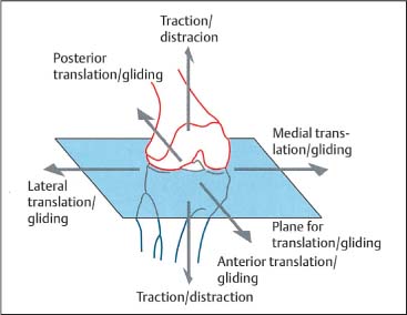
Fig. 2.4 Translatory motion directions.
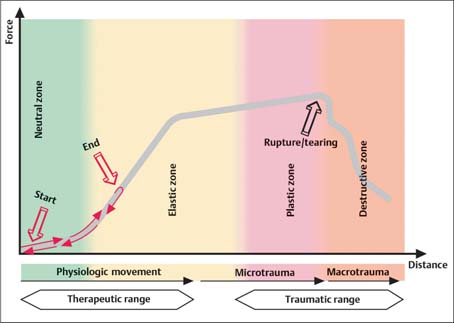
Fig. 2.5 Force–distance diagram depicting joint motion for roll–glide motion and translation in the physiologic and pathologic zones as applicable to synovial joints (peripheral joints as well as apophyseal or facet joints).
The Load–Displacement Diagram
The shape of the load–displacement curve is primarily determined by the following five factors:
• Architectural shape of each particular synovial joint or spinal segment.
• Mechanical properties of the hard (bone) and soft (cartilage, ligaments, tendons, joint capsule) tissues.
• Fluid mechanical properties (synovial fluid, cartilage).
• Joint motion characteristics (displacement type and direction).
• Rate of the applied forces.
The load–displacement diagram (Fig. 2.5) can be divided into four different “zones,” namely, the neutral, elastic, plastic, and destructive zones. The width of each zone is subject to large variation due to the following two major variables:
• Architecture and shape of the individual joint or spinal segment.
• Motion directions.
The Neutral Zone
In the neutral zone of a joint or spinal segment, the internal resistance to angular or translatory motion is reduced to a minimum. In nonpathologic situations, it is approximately 2% of the resistance at the extreme end of the elastic zone (Panjabi, 1992a).
The Elastic Zone
This zone reflects the behavior of the elastic properties of tendons and ligaments as they influence a joint’s motion characteristics under different loading situations. They primarily affect the roll-and-glide motion in a synovial joint while repositioning the joint’s center through the exploitation of coupled motions (Panjabi, 1992a).
When subjected to mechanical stress during the various loading situations associated with movement, the elastic structures are able to respond in a linear fashion, but only up to a certain point. Once the loading forces are removed again, the elastic structures return to their original length, or nearly so.
The Plastic Zone
If motion proceeds beyond the elastic zone, that is, beyond the elastic extreme allowed by the particular ligaments, tendons, and other soft tissues, it will inevitably cause a microtrauma in the elastic structures. Thus, in the plastic zone, the muscles, tendons, ligaments, and disks become essentially overstretched while their macroanatomy remains essentially intact.
The Destructive Zone
If a limb joint or spinal segment is carried or forced beyond the respective plastic zone, then it will be subjected to anatomic disruption, tears, fractures, or dislocations. This typically happens during injuries, where the ligaments and tendons are excessively engaged or “stressed”, forinstance. Thus, when entering this zone, the tendons and ligaments are unable to withstand the stress to which they are subjected and will begin to show structural changes ranging from partial tears to complete rupture. In a mechanical comparison, a rope, for instance, may tear even under relatively little stress with small loading forces if they are applied suddenly in a burst-like fashion.
The Zero-Force Barrier (ZFB)
The zero-force barrier marks the junction between the neutral and elastic zones. The internal forces resisting angular and translatory movement account for approximately 2% of those encountered at the extreme of the elastic zone as it approaches the plastic zone (Figs. 2.6, 2.7).
The Physiologic Barrier (PhysB)
The physiologic barrier of a synovial joint lies within the elastic zone. Thus, as long as the joint is subjected to motion up to but not beyond its physiologic barrier, its associated structures undergo only elastic deformation, which is generally reversible. The neutral zone remains unchanged (Figs. 2.6, 2.7).
The physiologic barrier represents the extreme of motion that can be reached by the patient’sown active movement. Further motion in the direction of the anatomic barrier is still possible but requires the introduction of additional force, such as that introduced when the examining physician passively guides the joint toward the anatomic barrier from where the patient’s active movement came to a stop.
The Anatomic Barrier (AB)
The anatomic barrier is located in the region between the elastic and the plastic zones. With passively induced movement—movement introduced not by the patient but the examiner—the anatomic barrier can be approached without causing microtrauma. Motion induced in a limb joint or joints of the spinal segment (e. g., facet joints) beyond the respective anatomic barrier will push the joint into the plastic zone, resulting at least in microtrauma if not macrotrauma (Figs. 2.6, 2.7).
The Actual Physiologic Barrier (APhB)
The actual physiologic barrier reflects the limit of motion encountered in the presence of altered, pathologic motion characteristics in a joint, such as hypomobility or hypermobility. This barrier can be engaged without necessarily involving microtrauma or macrotrauma (Figs. 2.6, 2.7).
The Pathologic Barrier (PB)
The pathologic barrier, also known as the restrictive barrier, reflects the deviation from the normal limitation of motion caused by bony and/or soft-tissue changes (Fig. 2.6). In a clinical setting, the motion is more often than not decreased in the form of joint hypomobility, while it can also be increased when there is laxity of a joint, for instance with associated hypermobility.
The Resting Position (R)
The joint’s or spinal segment’s resting position is maintained at that point or “range” where the joint play is greatest. Pathologic structural changes and abnormal muscle and tissue tension displace a joint’s or a spinal segment’s normal resting position. The resting position marks that location within the arc of normal motion where the joint volume is largest. Usually, in a clinical situation, pain intensity is registered by the patient as minimal in the resting position, which is also known as the present neutral position.
Treatment Plane of a Spinal Segment or Limb Joint
The plane of treatment is perpendicular to the traction direction. Gliding or articulatory type of mobilization in a limb joint is introduced according to the convex and concave rules.
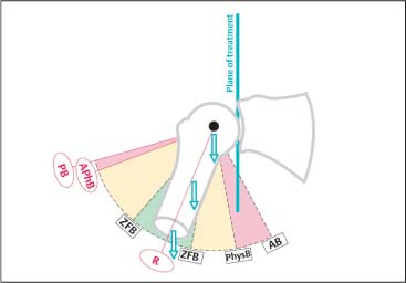
Fig. 2.6 Barriers of motion.
AB | Anatomic barrier |
APhB | Actual physiologic barrier |
PB | Pathologic barrier |
PhysB | Physiologic barrier |
R | Resting position |
ZFB | Zero-force barrier |
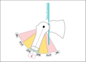
Fig. 2.7 Barriers of motion.
AB | Anatomic barrier |
PhysB | Physiologic barrier |
R | Resting position |
ZFB | Zero-force barrier |
Joint Localization at the Motion Barrier
When the joint or spinal segment is engaged at its respective motion barriers (e. g., in flexion/extension, side-bending right/left, and rotation right/left), joint play is reduced to a minimum, while at the same time joint stability is greatest.
Convex Rule
The convex rule applies to a joint in which the distal joint surface has a convex shape. If angular motion is restricted due to articular degenerative changes or other structural changes, for instance, the direction of the mobilization-without-impulse technique is usually opposite to that of the restricted joint mobility (Fig. 2.8).
Concave Rule
The concave rule refers to a joint in which the distal joint surface has a concave shape. If angular mobility is restricted due to articular degenerative changes or other structural changes, the direction of the mobilization-without-impulse technique is usually in the same direction as that of the joint restriction (Fig. 2.9).
Mobility Gain
With the pathologic barrier as a starting point for treatment, the mobility gained as a result of treatment is defined as the amount of newly gained angular joint mobility primarily due to increased muscle length upon the induced muscle stretch (Fig. 2.10). When a muscle crosses two or more joints, it may be useful to stabilize one joint while attempting to increase the mobility in the second joint during the stretch.
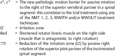
Provocation Testing
Mechanical stress directed to the various components of the locomotor system may lead to a number of nociceptive reactions which, ultimately, are reported by the patient as pain. Depending on the intensity, duration, and extent of and the neurophysiologic mechanisms evoked by these nociceptive reactions, the individual patient’s perception of the pain, both qualitatively and quantitatively, is subject to significant variation. Furthermore, the nociceptive reactions and pain alter muscle tone and/or autonomic functions in such away that ultimately they contribute to a self-perpetuating vicious cycle.
The clinical manifestation (sign) of the nociceptive reactions is the irritation zone. The finding of a specific irritation zone upon clinical examination helps to verify objectively the presence of a segmental dysfunction. Furthermore, the clinician is able to determine which motion direction exacerbates or improves the localized irritation zone, by introducing specific motions to the affected joint. Thus, the behavior of the irritation zone in response to the motions induced by the examiner, and in particular that of controlled provocative motion testing, is a helpful tool in the process of rendering a differential diagnosis and choosing the most appropriate treatment plan. (Fig. 2.11a, b).
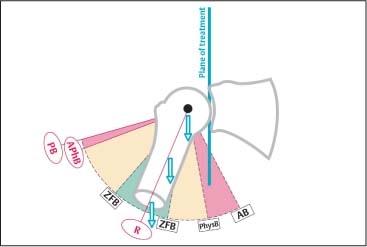
Fig. 2.8 Convex rule.
AB | Anatomic barrier |
APhB | Actual physiologic barrier |
PB | Pathologic barrier |
PhysB | Physiologic barrier |
R | Resting position |
ZFB | Zero-force barrier |
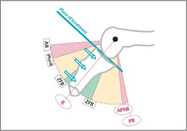
Fig. 2.9 Concave rule.
AB | Anatomic barrier |
APhB | Actual physiologic barrier |
PB | Pathologic barrier |
PhysB | Physiologic barrier |
R | Resting position |
ZFB | Zero-force barrier |
Biomechanical Principles and Their Clinical Correlation
In-vitro studies by Panjabi et al. (1994) and Grob et al. (1993) demonstrate that joint instability is typically associated with an increased neutral zone. Both increase and decrease in angular and translatory mobility can be associated with an increased neutral zone. An increased neutral zone is found both with hypomobility and with hypermobility. For instance, in cases where there are findings of advanced spondyloarthrotic/degenerative changes, the neutral zone can be increased, even though the segmental angular motion is diminished, e. g., the joint is found to be hypomobile. However, due to the loss of or reduction in elasticity of the associated soft-tissue joint structures, the neutral zone is increased. In another example, flexion-extension injury to the cervical spine in patients who have known underlying spondylotic changes can lead to traumatic overstretching of the soft tissues, pushing the joint (s) into the plastic zone or, worse yet, into the destructive zone. This increases the neutral zone, which can be clinically determined by testing the affected joint (s) for signs of instability: When the usually smooth roll-and-glide mechanism is impaired, sudden or abrupt mechanical stress forces will be transmitted directly to the bones, ligaments, and tendons. Because these structures can be viewed as “receptor organs,” they play a significant role in the coordination of motion and muscle tone. Any disruption in the interplay between smoothness of joint motion and loading forces can lead to clinically relevant nociceptive reactions and pain, which in turn can lead to changes in the normal movement patterns, ultimately leading to clinically observable muscular imbalances.
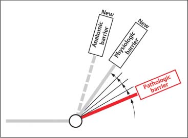
Fig. 2.10 Motion gains.
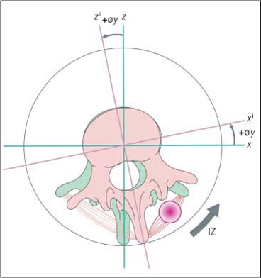
Fig. 2.11a Provocation testing.
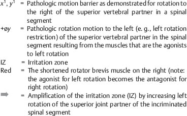
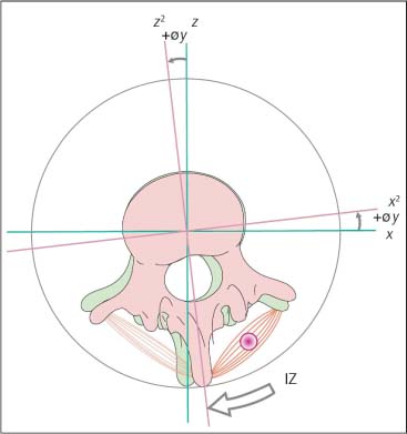
Fig. 2.11b Provocation testing.
Application of the Biomechanical Model to Various Therapeutic Modalities
Biomechanically, manual medicine procedures take place in the neutral and elastic zones only, and typically do not enter the plastic zone (Fig. 2.12).
Depending on the individual clinical situation, the goal of treatment is to restore normal joint play and/or restore as much of the normal range of motion as possible. If the forces introduced to a joint during a manipulative maneuver are inappropriately directed or are excessive, there is a real risk of damaging the joint and its surrounding tissues, especially when going beyond the joint’sanatomic barrier.
In certain clinical situations however, it may be necessary to move a joint into its plastic zone, for instance in certain manipulation procedures under anesthesia. Apart from this exception, it should otherwise never be the goal of manual medicine procedures to thrust any joint into the plastic zone and run the risk of causing macrotrauma (Fig. 2.13).
Potential Risks Associated with Manual Techniques: Biomechanical Considerations
Treatment Risk as Related to the Velocity of Mobilization Force
As discussed earlier, there is a fundamental biomechanical difference in the way a tendon is able to withstand varying loading conditions. If the loading force is applied in quick and abrupt bursts, e. g., intermittently but with high speed, then relatively little force is necessary to cause the tendon to tear, either partially or completely. If the loading force is introduced rather slowly and over a period of time, the chance of a tendon to tear is markedly reduced. Accordingly, it is reasonable to assume that the high-velocity, low-amplitude mobilization-with-impulse techniques (MWITH) have a much greater likelihood of causing irreversible damage than the mobilization-without-impulse techniques (MWOUT). Furthermore, the rapidity with which a high-velocity impulse force is introduced to a joint or spinal segment may be too sudden for the usual protective reflexes to respond. These two factors, the biomechanical properties of the tissues and the elimination of the protective reflexes, help explain how the MWITH techniques can thrust the facet joint into the destructive zone with the application of relatively little force.
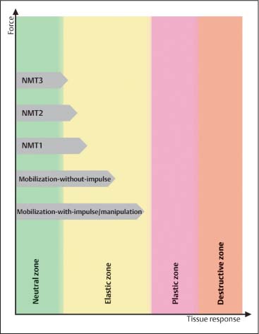
Fig. 2.12 The different force magnitudes utilized in mobilization and manipulation techniques.
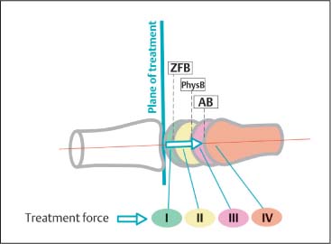
Fig. 2.13 Forces used in mobilization and manipulation techniques.
Treatment force I | up to ZFB (= Zero-force barrier) |
Treatment force II | up to PhysB (= Physiologic barrier) |
Treatment force III | up to AB (= Anatomic barrier) |
Treatment force IV | beyond AB |
Treatment Risk as Related to the Amplitude of Mobilization Force
If manipulative treatment introduces excessive forces and pushes the joint (s) beyond its/their respective anatomic barrier (s), there is a great risk of causing tissue damage, which can range from microtrauma to macrotrauma. These changes can include the following:
Microtrauma (Fig. 2.14)
• Increase of the neutral zone.
• Reduction in the quality of the roll-and-glide motion.
Macrotrauma (Fig. 2.15)
• Increase of the neutral zone.
• Adaptive, overcompensatory or even decompensatory changes in the associated joint structures, including the joint capsule and muscles, in an attempt control the loss of stability.
Treatment Risk as Related to Degenerative Changes Affecting Elastic Tissue Structures
Elastic tissue structures that demonstrate degenerative changes are characterized by a reduced ability to withstand stress, with an increased chance of structural failure. This is represented graphically in Fig. 2.16, which depicts a condensed elastic and plastic zone. Thus, in treating a patient who has known or suspected degenerative joint and/or soft-tissue changes, the mobilization maneuvers should be performed with as much care as possible and with as little force as necessary. This applies to both the thrusting (impulse) techniques and the nonthrusting techniques. Treatment must always pay attention to the specific joint’s altered or “reset” anatomic barrier (Fig. 2.16), beyond which treatment should not go.
The presence of osteophytes and spondylophytes may lead to an abrupt stop of the joint gliding motion. Inappropriate treatment with excessive force application may break these structures, inevitably leading to macrotrauma.
The elastic zone is decreased. Clinically, this implies the following:
• Hard end-feel.
• Loss of range of motion.
• Even small movements can bring the joint into the destructive zone.
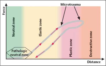
Fig. 2.14 Microtrauma.
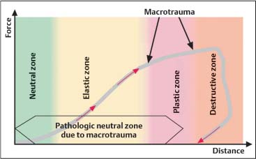
Fig. 2.15 Macrotrauma.
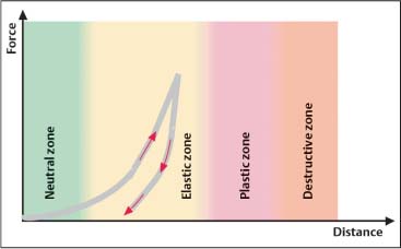
Fig. 2.16 Motion characteristics as a result of degenerative changes.
Degenerative Joint and Spinal Changes While the Neutral Zone is Increased
Instability
Degenerative joint changes along with osteophyte formation reduce the roll-and-glide as well as the gliding motion in a joint. Not only the articular surfaces are involved; the stabilizing structures within and surrounding the joint can also become affected. If subject to trauma these structures may be stretched beyond their normal length and ultimately lose their inherent elasticity (Fig. 2.17).
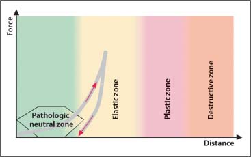
Fig. 2.17 Instability.
Related posts:
 Evidence Base in Manual Medicine for the Treatment of Back Pain Syndromes: Background, Status, and Practice
 The Pharmacologic and Psychologic Treatment of Chronic Pain
 Nonradicular Pain: Spondylogenic and Myofascial Pain Syndromes
 Myofascial Trigger Point Treatment
 Structural and Functional Diagnosis and Treatment of the Spine, Ribs, Pelvis, and Sacroiliac Joint
 Structural Diagnosis and Functional Treatment of the Limbs
Stay updated, free articles. Join our Telegram channel

Full access? Get Clinical Tree


