Fig. 14.1
Process workflow for custom implant design with interfaces to manufacture and precise placement technologies
To affectively visualise and understand this important factor, we must adopt 3D imaging techniques such as CT and MRI scans. The image sets from these modalities can then be used to gauge the bone and soft tissue quality and generate 3D models of affected bone and cartilage.
Image Processing
Software packages such as Mimics® (Materialise, Leuven, Belgium) and ScanIP® (Simpleware Ltd, Exeter, UK) generate masks of the patient’s bone, soft tissue and existing metalwork. This technique is often referred to as thresholding (Fig. 14.2). The Hounsfield units allow the software operator, in this case the implant design engineer to differentiate between areas of different density material to determine whether it is bone, soft tissue, PMMA cement, or existing implants which may be in-situ.
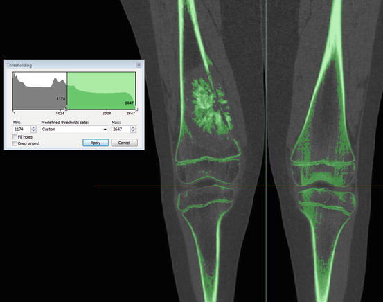

Fig. 14.2
Thresholding of bone in Materialise Mimics showing the bone tumour, the bone cortices and the growth plates in this skeletally immature patient
Often in revision scenarios where the implant in-situ is being removed, challenges in image processing and segmentation will arise. CT artefacts and scatter occur in the imaging due to the extreme heterogeneity of the metal and tissue in cross sections. If left ignored, these artefacts distort the image and make the segmentation impossible or inaccurate. The operator will require using a combination of image filtering techniques, anatomical knowledge, past experience to negate and compensate for these artefacts by manually thresholding each affected slice. This introduces an element of subjectivity and human error which, if accumulates over the whole length of the image, has the potential to affect the overall accuracy and reliability of the 3D models.
Once the imaging is sufficiently processed and the patient bone is sufficiently thresholded, the overall mask is then segmented into different bones (Fig. 14.3). This process is called segmentation and again, can be highly dependent and the operators skill and experience. These segmented masks can then be converted into 3D models of the bone (Fig. 14.4).
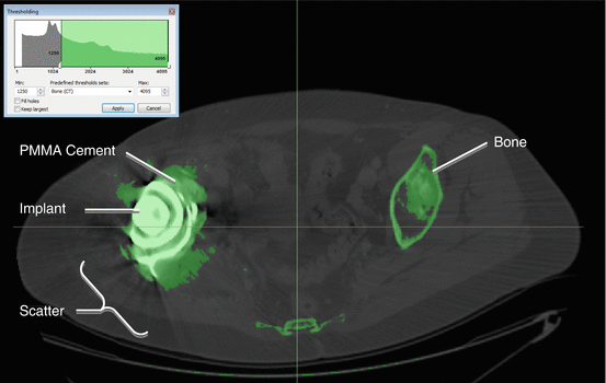
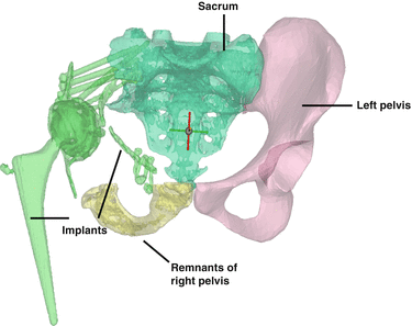

Fig. 14.3
Thresholding with artifacts and scatter caused by the implants in-situ

Fig. 14.4
The 3D models of the remaining pelvis, sacrum, implant and metal work
Implant Design
Pre-operative Planning
Once the 3D model of the bone is obtained, it allows for easier review of the patient’s condition and rotating the view enables closer inspection of the details. Having been presented with this data, it is then the surgeon’s responsibility to determine the oncological margins and associated resection levels. The surgeon communicates this with the design engineer through annotations on multiple images in various views. The design engineer will then translate these lines in to the 3D planning software representing the resection planes and segments the models further, in effect showing the plan, pre-resection and post resection (Fig. 14.5).
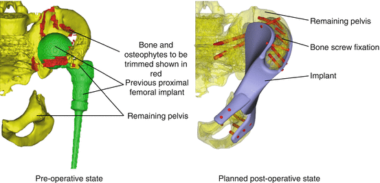

Fig. 14.5
Example of computer aided planning, showing the patients pre-operative state and the planned post-operative outcome
Modelling Implant Body
Once both the surgeon and engineer agree with the planning, the engineer can model the implant body. Many CAD techniques may be used from extruding and revolving, to more sophisticated sheet based and freeform modelling tools such as sweep along guides and cross sections (Fig. 14.6). In essence the engineer will create the implant body in the space that is left by the resection, usually as a simplified geometry of the bone being replaced.
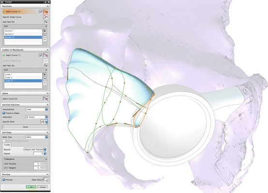

Fig. 14.6
Part of a Hemipelvis implant body being modelled in Siemens NX using the “Swept” tool
Modelling Fixation
The fixation of the device on to the bone and the interface between the two requires the design to be at its most precise. Typically when the resolution of images allow, fixation interfaces are designed to sit as close as 200 μm to the bone, without interference. The type of fixation used varies depending on the skeletal location, age of the patient, quality and geometry of remaining bone, and the loading the implant body will sustain.
Both cemented and cemented intramedullary stems are often used when fixing into the medullary canals of long bones. However the choice between cemented and uncemented is largely dictated by the skeletal location, patient age, quality of bone and the surgeon’s preference. For shorter fragments of bone, such as joint saving implants, short internal fins, and extra-cortical plates are often used. Bone screws are used to achieve immediate short-term fixation between the extra-cortical plates and bone. However as the bone grows across the interface and on to the HA coated implant and extra-cortical plates, the loading is transferred from the screws on to the plates. Extra-cortical plates are also used in pelvic and acetabular reconstructions, again with the aid of HA coating and bone to achieve sufficient fixation (Fig. 14.7).
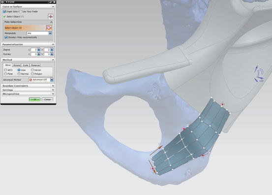

Fig. 14.7
Modelling extra-cortical plates to match contour of the bone in Siemens NX using the “X-Form” tool
Once the design process is complete, it is presented to the surgeon. The implant model is converted to a 3D portable document file (pdf) along with the model of the bone, allowing the surgeon to closely inspect the implant in relation to the bone. Any further changes are made and the design is finalised. At this stage the manufacturing drawings are detailed and ready for production.
Finite Element Analysis
Currently finite element analysis is not used to evaluate designs for patient specific cases. The many simplifications, unknowns and sources of error are all factors that, when combined, equate to unreliable results that add little value to the design process. The time consuming nature of meaningful FEA also makes it impractical for application to urgent patient specific limb salvage cases.
Manufacturing
The two most common manufacturing techniques for complex implants are through the more traditional CNC (Computer Numeric Controlled) techniques and the increasingly popular route of AM. The machining path is considered by the design engineer during the design process, as it could become a limiting factor in the design, if the degree of complexity of the design prevents it from being manufactured.
CNC Milling
The CAD model of the file is converted to numerical commands for CNC milling machines via a post processor. These commands then control the path of the tool, cutting away excess material from a bar of metal until the required shape of the implant is remaining. Multi-axis CNC machines allow for more complex shapes to be achieved without manual intervention by the operator. They also typically allow for an enhanced surface finish of complex surfaces than conventional 3 axes machines. Support structures to aid the stability of component whilst being machined are often modelled on to the implant to allow for further processes such as drilling of holes or manual finishing of the implant such as polishing.
ALM
ALM technology presents the designer with fewer limitations on the complexity of the design, as it allows for shapes to be fabricated layer by layer, using either a focused laser or electron beam to melt a layer of Ti-6Al-4 V or Co-29Cr-6Mo alloy powder. The selected layer portions which are melted are then added to the build direction until the final geometry of the implant is built. This manufacturing technique allows for the designer to explore new ways of achieving better fixation. For example, the placement of porous regions along the interface allows for greater possibility of bony in-growth on to the implant. Furthermore, by introducing porous scaffold and attempting to match the stiffness of the bone the engineer can attempt to prevent the phenomena of stress shielding. While ALM is a vital tool for manufacturing freeform and organic shapes, it still requires manual processing in the form of removing support struts, cleaning up holes and polishing.
Coordinate Measurement Machine (CMM)
As the complexity of implant designs increase, quality-control inspection and verification becomes more challenging using conventional methods. The latest CMM technology allows for 3D verification of the implant against the CAD model, enabling quality engineers to quickly and efficiently determine deviations from the model.
Patient-Specific Cutting Jigs
In order for surgeons to replicate difficult resection planes and osteotomies, the design engineer can produce patient specific cutting jigs. These jigs allow for the surgeons to achieve a cut in the exact position and orientation as planned during the design phase, ensuring a precise match between the remaining bone and implant. Correct positioning of the jig is achieved by designing the contact surface to match the exact contour of the bone, so the inside surface of the jig locks against the bone. Once positioned correctly, bone pins are inserted through a choice of holes in various positions into the bone in order to fix the jig in place. The jig features slots with boundaries that constrains the surgeons’ oscillating saw to the plane of the planned resection (Fig. 14.8).
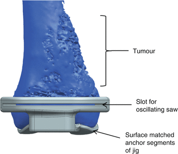

Fig. 14.8
A cutting guide for a distal femoral joint saver
These jigs enable the surgeon to be much more adventurous with their planning and allows for multi-planar resections to be made considerably easier. This in turn allows the designer to design more sophisticated implants. One particularly useful application of such jigs is for joint saving distal femoral implants (Fig. 14.9). With tumours that are relatively close to the joint, but not affecting the adjacent bone, surgeons tend to not only remove the affected bone, but also sacrifice the joint. However, provided that the surgeon can achieve an adequate resection margin from the tumour, the joint can be preserved and the design engineer can produce a design which features extra-cortical plates which encapsulate the remaining bone along the periphery, with additional internal fins and hydroxyapatite coating which encourage bony in-growth on to the implant. The cutting jigs prove their worth in this scenario, as even the slightest discrepancy between the planned resection and achieved cut means that the implant may not fit. This is due to the cross sectional profile of the bone varying considerably depending on the position and orientation of the cut.
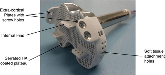

Fig. 14.9
Distal end of an anatomically-shaped distal femur joint saving implant
Navigation and Robotics
The design engineer can also interface with navigation and robotic assisted surgeon equipment. It is crucial that the 3D geometry design is faithfully transferred and therefore it is essential that implant designers and navigation/robotic systems develop work closely together to have a common language and standard points of reference.
Stay updated, free articles. Join our Telegram channel

Full access? Get Clinical Tree


