, Ardiyansyah Syahrom2 , Muhamad Noor Harun2 and Mohammed Rafiq Abdul Kadir3
(1)
Department of Applied Solid Mechanics and Design, Universiti Teknologi Malaysia, Johor, Malaysia
(2)
Sport Innovation and Technology Centre (SITC), Universiti Teknologi Malaysia, Johor, Malaysia
(3)
Faculty of Biosciences and Medical Engineering, Department of Clinical Sciences, Universiti Teknologi Malaysia, Johor, Malaysia
Abstract
Three-dimensional (3D) models of a right ankle TAR have been created to represent Bologna-Oxford (BOX) TAR model. Finite element analysis of ankle stance phase of gait cycle was developed to simulate the static response behaviour and extract the data in determining the contact pressure on contact surface of the bearing and talar components. Sliding distance was determined by predominate motion of plantar/dorsi flexion of ankle stance phase gait cycle. Validity of contact analysis was conducted to make sure consistent, accurate, and therefore dependable procedures.
Keywords
Contact pressureTotal ankle replacementFinite element analysisBOXSliding distance2.1 Geometric Model
A three-dimensional (3D) model of a TAR was built using the computer-aided design (CAD) tool, SOLID WORKS. The BOX TAR was used throughout this simulation. The model of BOX TAR was chosen with regards to the shapes of the three components which were congruence with physiologic ankle mobility, the natural role of the ankle joint ligaments and encouraged early clinical result that demonstrated safety and efficacy [1, 2]. Figure 2.1 shows the dimensions of BOX TAR.
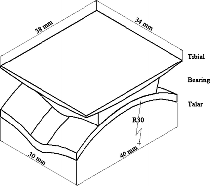

Fig. 2.1
Implant geometry
This model was developed to simulate the right ankle TAR. The metal parts of the tibial and talar components were assigned to be of Cobalt-Chromium (CoCr) material properties with titanium coating sprayed on articulating surfaces where the Young’s modulus of 210 GPa and Poisson’s ratio of 0.3 were applied to the model [3]. The tibial component with a spherical surface of 130 mm radius has contact with the bearing component which allows rotations [4]. The talar and bearing components have a concave sulcus of 35 mm radius where the bearing on the inferior surface is intact with talar components which is fully conformed to the bi-concave surface [5]. The thickness of the bearing varied in 1-mm increment from 5 to 8 mm [5]. The bearing component is ultra-high molecular weight polyethylene (UHMWPE) material manufactured from compression moulded from GUR 1020 with Young’s modulus of 500 MPa and Poisson’s ratio of 0.3 [5].
2.2 Finite Element Analysis
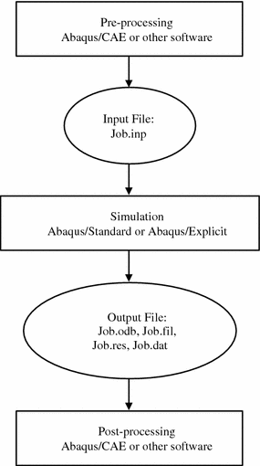
The finite element analysis is a numerical method to solve many problems in engineering and mathematical physics. The rapid development of computer technology encourages the use of finite element analysis as a method to solve various areas of problems. The utilization of finite element software is very useful for problems with complicated geometries, loading, and material properties, where analytical solutions are not available. Basically, there are three stages involving computer aided engineering (CAE) to complete the analysis [6]:
i.
Pre-processing—define the physical problem of the model included.
ii.
Simulation—background process that solves the numerical problem defined in the model.
iii.
Post-processing—evaluate the results obtained.
These three stages are linked together as shown in Fig. 2.2. This study on the development of computational wear prediction on total ankle replacement (TAR) was analysed using ABAQUS/CAE v6.09.
2.2.1 Development of Finite Element Analysis of Gait Cycle
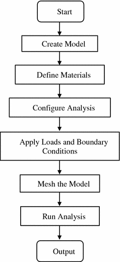
The finite element analysis is potential in making wear predictions. It is able to accurately consider both the variation of the loadings and the continuous change of the geometry caused by material removal in complex three-dimensional components. The computational simulation of wear prediction on total ankle replacement (TAR) simulated the static response behaviour of an ankle gait cycle which was conducted by using Abaqus/Standard. Wear prediction simulation used finite element analysis to extract the data in determining the contact pressure on contact surface of the bearing and talar components. The contact surface of the bearing and talar components were used to simulate wear because the sliding distance on contact surface of tibial and bearing components were relatively small (almost zero) and produce no wear. These reflect to the kinematics of ankle joint. The finite element analysis was used to visualize the wear prediction behaviour. The following steps in Fig. 2.3 simulate the BOX TAR model.
2.2.1.1 Create Model
The BOX TAR model consisted of three components which were tibial, bearing and talar. The details of this model geometry were explained in Sect. 2.1. The BOX TAR was modelled in SOLIDWORKS, a computer aided design (CAD) software. The model was converted to .SAT format which was compatible to the commercial ABAQUS software created in order to generate the model in the ABAQUS/CAE tool.
2.2.1.2 Define Materials
All components generated required the definition of the material properties. The Young’s modulus and Poisson’s ratio were defined in the property module of the ABAQUS/CAE software. The tibial and talar components were assigned to be of Cobalt-Chromium (CoCr) where the Young’s modulus was 210 GPa and the Poisson’s ratio was 0.3. The bearing component was assigned to be of ultra-high molecular weight polyethylene (UHMWPE) where the Young’s modulus was 500 MPa and the Poisson’s ratio was 0.3.
2.2.1.3 Configure Analysis
In this simulation, the static responses were used. This is a single event that needed single analysis steps. Overall, the analysis consisted of two analysis steps where-by the ABAQUS/CAE generated an initial step automatically. The analysis step was created in the period of 0.625 s. The time period was determined by stance phase of time taken in the ankle gait cycle [7]. Stresses, displacements, and contact were requested in the field output while the energy was requested in the history output. All outputs requested for a whole model every 0.025 units of time. The output data required was contact pressure where by it was printed in the form of tables that was written in ABAQUS data (.dat) files.
The interaction was created using surface-to-surface contact, in which the contact property used was tangential behaviour. The friction coefficient between two articulating surfaces of the metal and bearing components were assumed to be 0.04 [8].
2.2.1.4 Apply Loads and Boundary Conditions
The tibial component was fixed in the distal tibia bone and the talar component was fixed at the articulating surfaces of the talar bone. In this simulation, the load created was an axial (vertical) load using concentrated force applied to the tibial component. The boundary condition of internal/external rotation was applied to the tibial component whereas the anterior/posterior force and plantar/dorsiflexion were applied to the talar component. The variation of load and boundary conditions of the stance phase of ankle gait cycle applied was utilized by creating tabular amplitude. The talar component was constrained using a tie at a point that was the center of articular surface of the talar dome as shown in Fig. 2.4. The applied boundary conditions and force predictions were based on previous work [9, 10]. Time histories of boundaries and force predictions of the stance phase of the gait cycle was considered to simulate wear predictions on the TAR model as shown in Fig. 2.5. The stance phase of gait cycle was divided into 25 instants.
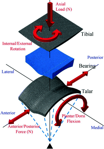
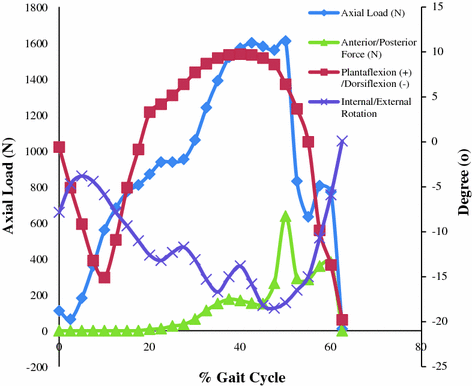

Fig. 2.4
Load and boundary conditions configuration on finite element simulation model

Fig. 2.5
Time histories of applied boundary conditions and force predictions of stance phase
2.2.1.5 Mesh the Model
There are hexa, wedge and tetra elements for the solid mesh element available in ABAQUS/CAE. Tetrahedral elements are geometrically versatile and used in many automatic meshing algorithms. It is very easy to mesh a complex shape with tetrahedral elements. It is known as a robust element and occasionally used as a rigid element. The hexahedral elements normally provide a good mesh with a solution of equivalent accuracy at less cost. However, tetrahedral elements are less sensitive to initial element shape, whereas first-order hexahedra perform better if their shape is approximately rectangular.
The metal parts of the tibial and talar components were modelled as four nodes which were three-dimensional tetrahedral elements represented as rigid triangles. The number of elements was 36,457 and 16,224 respectively. The tetrahedral element was stiffer than the hexahedral element. This was due to more points of integration in the hexahedral element than the tetrahedral element. Thus, the tibial and talar components, as hard parts, were assigned to use the tetrahedral element while the UHMWPE bearing was assigned to use 5760 element of eight node hexahedral elements as soft part.
Stay updated, free articles. Join our Telegram channel

Full access? Get Clinical Tree


