Fig. 19.1
3D bone surface models of the entire bilateral radius and ulna are created from 1.25-mm CT data. CT slice (a), segmentation of the radius (b) and 3D bone surface model of the radius (c)
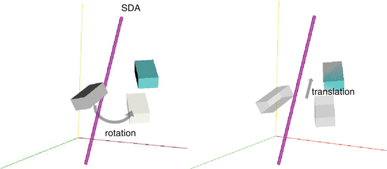
Fig 19.2
In a 3-D space, motion of every body can be expressed in terms of rotation around and translation along one unique axis or the screw displacement axis (SDA)
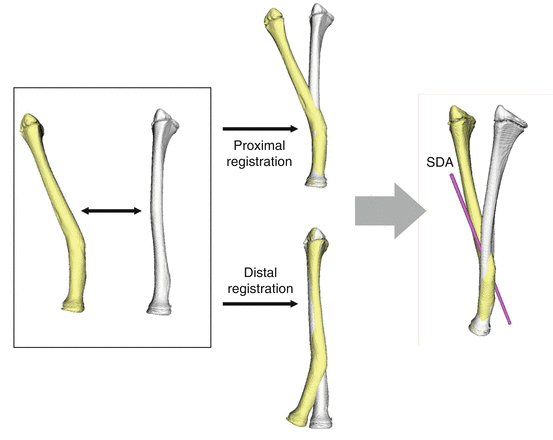
Fig. 19.3
The proximal part of the malunited bone (yellow) was superimposed with the corresponding part of the mirror image of the contralateral normal bone (white). The same procedure was then used for the distal part. By calculating the difference between the positions of the proximal and the distal parts, we acquired a matrix for the displacement, i.e., deformity of the distal part relative to the proximal part. This displacement can be further defined in terms of rotation around and translation along and a certain axis using the screw displacement axis (SDA) technique, respectively. Thus, bone deformity can be determined as the rotation around and translation along a single unique axis. When the translation is small, the SDA can be simply regarded as the deformity axis
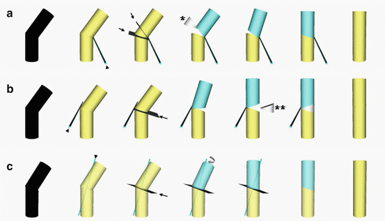
Fig. 19.4
The bended cylinders stand for the deformed bones. Different deformities would show similar silhouette (the left figures of a, b and c). Three-dimensional relation between the bone and deformity axis (arrow head of each figures) suggests the most appropriate method of correction. When the axis runs along the concave side of the deformity, a closing osteotomy after removal of a wedge (asterisk) brings about the rotation of the bone segment around the deformity axis thereby completes the correction (a). When the deformity axis is along the convex side, an opening wedge osteotomy followed by wedge-shaped bone grafting (double asterisks) is considered appropriate (b). When the axis is nearly parallel to the longitudinal bone axis, a rotational osteotomy (curved arrow) can be conducted along on the osteotomy plane, which is perpendicular to the deformity axis (c). If the deformity axis is displaced from the bone, closing/opening wedge osteotomy with shortening/lengthening is appropriate. Osteotomy planes are indicated by arrows
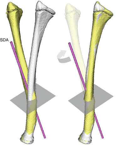
Fig. 19.5
Correction in this case is to be completed by performing a rotational osteotomy of 45° around the axis (SDA) on the plane perpendicular to it (curved arrow) because SDA is nearly parallel to the longitudinal bone axis
Design and Manufacturing of Patient Matched Instrument (PMI)
To reproduce the preoperative simulation in the actual surgery, a PMI with guiding holes for Kirschner wires and an osteotomy slit is designed on the basis of a 3D computer simulation using commercially available software (Magics RP; Materialise, Leuven, Belgium or Space-E; NTT Data Engineering Systems Corp., Tokyo, Japan) (Fig. 19.6) [13, 32]. PMI is shaped to closely fit the bone surface while the slit guides accurate osteotomy, and 2 sets of Kirschner wires, inserted through the drill-holes at an angle to the deformity, indicate that reduction is complete when they align parallel to each other. The PMI is then embodied as a plastic model through rapid prototyping machine (Eden250; Objet Geometries, Rehovot, Israel or Formiga P100; Electro Optical Systems GmbH, Munich, Germany) with medical grade plastic material. A reduction guide is prepared preoperatively to maintain the parallel position of the Kirschner wires in the same manner as for the PMI (Fig. 19.7).
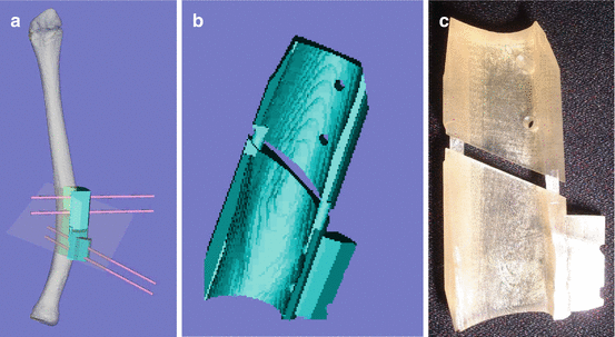
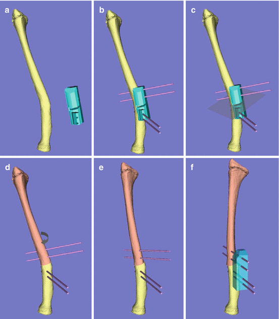

Fig. 19.6
A PMI, which has a shape to exactly fit the bone surface, an osteotomy slit and guide holes for K-wires, is designed (a, b) and embodied as a plastic model through rapid prototyping machine (c)

Fig. 19.7
After putting the PMI on the bone surface, it is fixed with Kirschner wires through the drill holes (a, b) and the bone is divided through the cutting slit (c). The PMI is removed (d) and the two sets of the Kirschner wires are brought into a parallel status to each other by rotating the distal segment (curved arrow, e). A reduction guide is used to maintain the reduced position (f)
Surgical Technique
The radial and ulnar diaphyses are each exposed through separate incisions as appropriate. PMI is then fitted closely onto the surface of the bone and fixed with Kirschner wires inserted through the guiding holes in PMI (Fig. 19.8). After completion of osteotomy with a bone saw applied through the cutting slit, a reduction guide is used to maintain the Kirschner wires in a parallel position for each bone. Internal fixation is then accomplished with a plate and screws (Fig. 19.9).
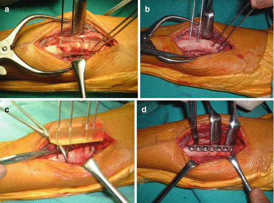
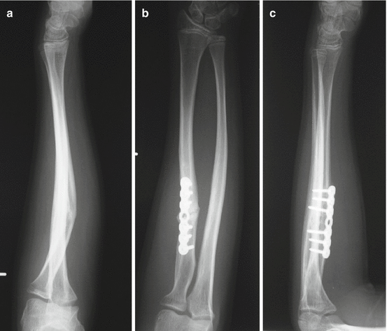

Fig. 19.8
The malunited radius is exposed through the anterior approach. PMI was fitted to the osteotomy site and is fixed it with Kirschner wires (a). The bone is divided through the cutting slit on the PMI, which was then removed (b). A reduction guide is used to maintain the Kirschner wires to be parallel (c). Internal fixation is accomplished with a plate and screws (d)

Fig. 19.9
A preoperative radiograph of a 13-year-old boy with malunited diaphyseal fracture of the radius who complained restricted forearm supination. The radius showed a 25° angular deformity at the middle third (a). The postoperative AP (b) and lateral (c) radiographs show good anatomical correction
Clinical Outcomes
The results of previous clinical study with 20 patients operated with this technique showed that the average radiographic deformity angle preoperatively is 21° (range, 12–35°) compared with the normal arm; this is improved to 1° (range, 0–4°) postoperatively [11]. The mean arc of forearm motion significantly improved from 76° preoperatively to 152° postoperatively. However, forearm supination was still restricted by ≥70° in 3 patients whose age at initial injury was <10 years and who had longstanding malunion of ≥96 months. Painful recurrent dislocation of the ulna and radial head resolved or decreased in 4 patients. Average grip strength improved from 82 to 94 % of that of the normal side. Preoperative pain disappeared or decreased substantially after surgery.
Cubitus Varus Deformity
Cubitus varus deformity is a malunion of the distal end of the humerus that generally includes varus, internal rotation, and hyperextension deformities [5, 36, 37]. In the past, it was considered a cosmetic problem, and correction of varus deformity alone is an accepted practice [18, 38]. Recently, because joint laxity [17, 39] and tardy ulnar nerve palsy [40] have been reported to be late complications, several investigators have advocated that correction of angular deformity is not enough and that rotational deformity should also be corrected [5, 36]. The previously reported 3D correction, however, was based on preoperative planning using data from plain radiographs and changes in the range of shoulder motion [5, 36, 37]. This procedure was also criticized for its technical difficulty and poor bone contact at the osteotomy site [18]. In contrast, the computer simulation system provides a simple and accurate correction based on 3D data. The contact area at the osteotomy site can be easily visualized using 3D images, which allows practical planning.
Deformity Evaluation of Cubitus Varus Deformity
The bone models of a patient’s upper arms and forearms are obtained from the CT data acquired in the same manner that was described in the forearm section.
The proximal part of the mirror image of the normal humerus, which is considered the target model, is superimposed manually on the corresponding part of the affected humerus followed by semiautomatic registration [15, 41, 42]. The same procedure is applied to the distal part. In manual registration, the greater tuberosity, humeral head, and shaft are set as the references for the proximal part and the medial and lateral epicondyles and distal articular surface for the distal part. When morphological change is present at the distal humerus, the proximal parts of the forearm bones were also used as references. Next, the 3D amount of deformity is quantified by subtracting the distance value of the distal humerus from that of the proximal humerus. Then the 3D amount of correction, which is the inverse of the deformity amount, is calculated and used for simulation of deformity correction. The correction amount is 3D data that includes varus–valgus, flexion–extension, rotational, and translational elements (Fig. 19.10).
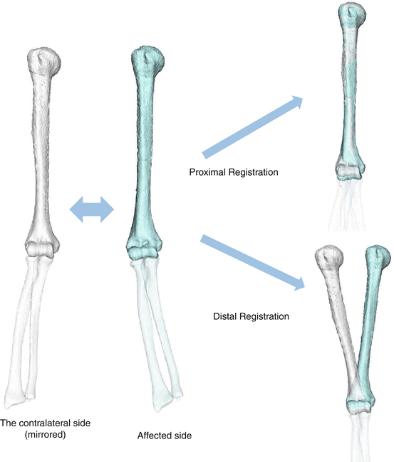

Fig. 19.10
Evaluation of the deformity in 3-D by comparing the affected humerus to the mirror image of the contralateral normal humerus. The proximal part of the mirror image of the normal humerus, which is considered the target model, is superimposed on the corresponding part of the affected humerus (proximal registration). The same procedure is applied to the distal part of the humerus (distal registration). Then the computer software automatically calculates the 3-D amounts of deformity and correction using the transformation data required for the distal and proximal registration
Simulation for Deformity Correction of Cubitus Varus Deformity
To plan the operation, the following simulation is made (Fig. 19.11) [15]. The distal osteotomy plane (DOP), roughly parallel to the distal articular surface, is set just proximal to the olecranon fossa of the bone model of the affected humerus. DOP is then moved by the correction amount described in the previous section and defined as the proximal osteotomy plane. The wedge-shaped segment cut out by DOP and POP is removed from the affected humerus. Then the simulation of 3D correction is completed by moving the distal segment of the humerus together with the forearm bones by the correction amount. In cubitus varus deformity after supracondylar fracture, the affected humerus is usually overgrown. This type of closing wedge osteotomy accompanied by derotation can accordingly bring about correction of both length discrepancy and angular- rotational deformity. For cases with gross internal rotation deformity, complete rotational correction may decrease the contact area at the osteotomy site to an extent where bony union would be of concern. In that case, the rotational correction is decreased, leaving a residual rotational deformity less than 15° for those cases.
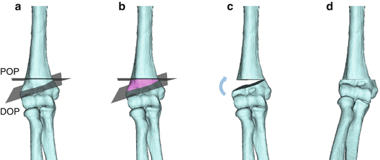

Fig. 19.11
The distal osteotomy plane (DOP), roughly parallel to the distal articular surface, is set just proximal to the olecranon fossa of the bone model of the affected humerus (a). DOP is then moved by the correction amount described in Fig. 19.10 and defined as the proximal osteotomy plane (POP, b). The wedge-shaped segment cut out by DOP and POP is removed from the affected humerus (c). Then the simulation of 3D correction is completed by moving the distal segment of the humerus together with the forearm bones by the correction amount (d)
PMI is manufactured to help reproduce the simulation in the actual surgery (Fig. 19.12). PMI has a shape that closely fits the characteristic surface of the posterolateral distal humerus including the lateral epicondyle and lateral half of the olecranon fossa. It also has 2 osteotomy slits and 4 drill holes. The slits guide the precise osteotomy cut; and 2 sets of 2 Kirschner wires, inserted through the drill holes at an angle to the deformity, indicate that the reduction is completed when they become parallel to each other. A reduction guide to maintain the parallel position of the Kirschner wires is prepared preoperatively in the same manner as the PMI (Fig. 19.4a–h).
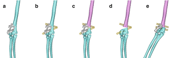

Fig. 19.12
PMI is placed onto the posterolateral surface of the distal radius (a) and fixed with K-wires (b). Osteotomy is performed through the slits (c) and PMI is removed leaving the Kirschner wires in place followed by resection of a wedge-shaped bone created by the osteotomy (d). The planned correction is achieved by bringing the Kirschner wires into parallel status, which is then held with a reduction guide (e)
Surgical Technique
A posterior approach with the patient in lateral decubitus position is employed. The PMI is placed onto the posterolateral surface of the distal humerus (Fig. 19.13). After placement is carefully assured by checking that all edge of the guide exactly contacted the bone surface, it is fixed with Kirschner wires of diameter 1.5–2.0 mm inserted through metal sleeves mounted on the PMI and osteotomy is performed with a bone saw through the slits. The PMI is then removed leaving the Kirschner wires in place followed by resection of a wedge-shaped bone created by the osteotomy. The planned correction is achieved by bringing the Kirschner wires into parallel status, which is then held with a reduction guide. While the correction is being maintained, Kirschner wires or tension-band wiring are used for internal fixation for the cases with open physes, bilateral plate fixation is applied for the cases with closed physes (Fig. 19.14). After the operation, a removable long arm splint is applied for 1–2 weeks for the plate fixation group and 3–4 weeks for the K-wire fixation group with 90° elbow flexion, and active and passive ROM exercise is started (Fig. 19.15).
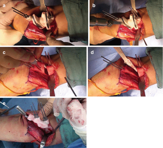
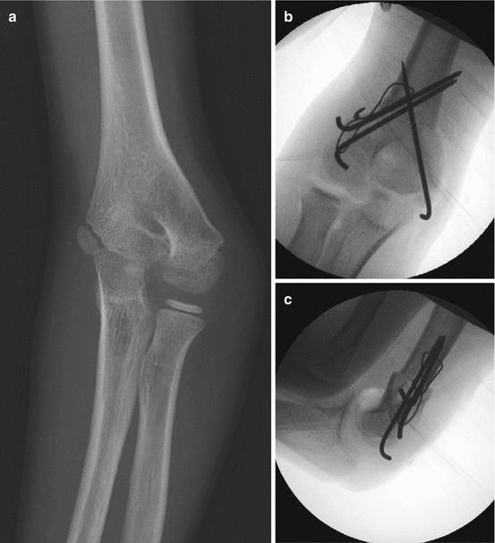
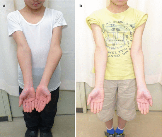

Fig. 19.13
A posterior approach with the patient in lateral decubitus position is employed. PMI is placed onto the posterolateral surface of the distal humerus and fixed with Kirschner (a). Osteotomy is performed with a bone saw through the slits (b). The PMI is then removed leaving the Kirschner wires in place followed by resection of a wedge-shaped bone created by the osteotomy (c, d). The planned correction is achieved by bringing the Kirschner wires into parallel status, which is then held with a reduction guide (e)

Fig. 19.14
Preoperative (a) and Postoperative (b, c) radiographs of a 10-year-old boy with left cubitus varus deformity

Fig. 19.15


Deformity correction for cubitus varus deformity. Preoperative (a) and postoperative (b) appearances
Stay updated, free articles. Join our Telegram channel

Full access? Get Clinical Tree


