Fig. 3.1
The software HipMotion predicts the acetabular and femoral sources of impingement. Reproduced from Tannast et al. [32] with permission from John Wiley & Sons, Inc.
Kubiak-Langer et al. further validated this model by surgically simulating femoroacetabular osteoplasty within the system [31]. They demonstrated predictable decreases in flexion, internal rotation at 90° of flexion, and abduction in those with FAI and subsequently significant improvements in these parameters after virtual resection of the osseous lesions. Limitations within these models do exist, however. The system currently incorporates only osseous structures and foes not take into account the hip joint’s surrounding musculature and ligaments and their effect on hip motion. This system also depends on concentric joint geometry, which allows a reliable determination of the femoral head center of rotation. Dysplastic and osteoarthritic hips presents challenges to this requirement as their inconsistent and nonconcentric morphology make predictive rotational and translational motion difficult. Although HipMotion was not directly linked to a surgical navigation system, it nevertheless represents a useful tool for the development of future computer-navigated technologies in hip arthroscopy.
Brainlab Hip CT
Brunner et al. developed Brainlab Hip CT (modified version of Brainlab Hip CT, Brainlab AG, Feldkirchen, Germany), a computer-navigated system utilizing CT imaging to assess head-neck offset correction after resection of cam-type FAI lesions [30]. This navigation system generated a 3D image of the hip based on preoperative CT scans, allowing the surgeon to cross-reference with intraoperative fluoroscopy. Real-time visualization of instrument position in relation to the head-neck junction and cam lesion during the procedure was therefore made possible (Fig. 3.2). The authors prospectively evaluated and treated 50 study patients with cam FAI randomly assigned to differing experimental cohorts, 25 patients assigned to a navigated treatment group and 25 to non-navigated treatment. Preoperative CT scans of the pelvis and postoperative MRI imaging were compared to determine if there was a significant reduction in the alpha angle after hip arthroscopy. The treatment was considered successful if a post-operative alpha angle less than 50° or an absolute reduction in the alpha angle greater than 20° was observed. The mean alpha angle was reduced from 76.6° to 54.2° after hip arthroscopy with Brainlab Hip CT, however, six patients in each cohort failed to demonstrate adequate femoral head-neck restoration of offset (12/50 = 24 %). Stemming from these results, Brunner et al. determined that the magnitude of alpha angle correction was not reliably improved with a computer-based navigation system as compared to controls. Of note, however, there were no significant differences in clinical outcomes among patients with adequate alpha angle reduction and as compared to patients who did at a mean follow-up of 26.5 months. This raises the question of whether post-operative alpha angle is an adequate predictor of clinical success. The limitations of this study include the relatively short-term follow-up as well as the utilization of pre-operative CT for 3D modeling and alpha angle measurement while subsequent alpha angle postoperative comparisons were made on 2D MRI studies.
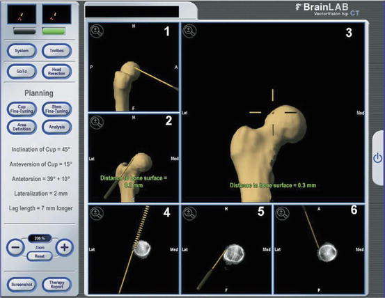
Fig. 3.2
The screen shows the position of the surgical instrument in relation to the femoral neck (frame 1, lateral 3-dimensional view; frames 2 and 3, anteroposterior 3-dimensional views; frame 4, anteroposterior 2-dimensional view; frame 5, lateral 2-dimensional view; and frame 6, transversal 2-dimensional view). The scripture at the right part of the screen represents a residuum of the original Hip-CT program and is not used in navigated hip arthroscopy. Reproduced from Brunner et al. [30] with permission from Elsevier.
Computer-Aided Navigation Using Encoder Linkages for Position Tracking
Monahan and Shimada developed and tested a computer system that utilizes a set of linkage encoders that are attached to the surgical instrumentation and to an anatomical reference base pin, providing increased visual feedback to the surgeon in real time (Fig. 3.3) [29, 33]. This computer-aided navigation system uses the encoder linkage to determine arthroscopic tool position in relation to the patient’s anatomic structures [33]. The base pin is implanted in the patients’ pelvis and acts as the connector between the linkage system and the patient. 3D reconstructions of preoperative CT or MRI imaging data are utilized to render a model of the patient’s anatomy, including critical neurovascular structures. This allows the surgeon to visualize and appreciate soft tissue entities that must be protected during hip arthroscopy. The authors created a physical hip model which included simulated plastic skin and a cotton filling to mimic soft tissue resistance, ten participants were then subsequently instructed to visualize two targets on the femur utilizing an arthroscope linked to the encoder system. Recorded measures included time for task completion and tool path distance based on the 3D coordinates of the arthroscope throughout each simulation. After completing the simulation both with and without the computer-aided navigation encoder linkage system, there was an average 38 % reduction in the time to task completion and an average 71.8 % decrease in tool path length with the navigation system. While there are clear benefits to decreasing tool motion during a hip arthroscopy procedure, such as a decreased risk of damage to soft tissues and neurovascular structures, the authors acknowledge there is much room for improvement in computer-aided hip navigation, including better visual display of the tool position alongside the camera display, and obtaining input and feedback regarding the system from experienced, adept hip arthroscopists.
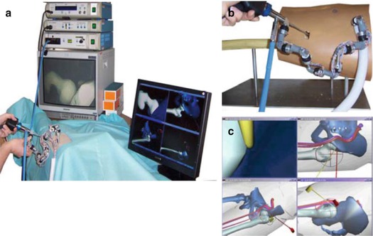
Fig. 3.3
Computer-Aided arthroscopic hip surgery system from Gunay et al. [34]. (a) Setup of complete computer-aided system. (b) Encoder linkage tracks an arthroscopic camera applied to a hip joint model. (c) Snapshot of computer display which shows the surgical tools and patient anatomy from multiple angles. Reproduced from Monahan et al. [33] with permission from IOS Press.
The Equidistant Method
Puls et al. developed a novel in-vitro hip joint simulation algorithm termed “the equidistant method” to detect the location and size of FAI lesions [29]. This system calculates a dynamic hip center of rotation instead of a predefined, fixed center of rotation as used in the other algorithms. To validate this method, the authors utilized artificial but anatomically correct pelvis and femur models (Sawbones, Pacific Research Laboratories, Vashon, WA), simulating the pathological cam and pincer lesions and subsequently their dynamic impingement point by creating modifications to the head-neck junction of the proximal femur and to the rim of the acetabulum. Based on these physical models, computer simulated 3D renderings were created. The physical pelvis model was rigidly fixed in space and a 3D coordinate system was subsequently created utilizing specific anatomic landmarks (i.e., anterior superior iliac spine, anterior inferior iliac spine, etc.) to register the plastic bones with their respective digital computer models. These models were then taken through various paths of motions and were subsequently recorded through a computer navigation system. Areas of impingement were identified, and four simulation algorithms (equidistant, simple, constrained, and translated) were applied to the motion paths and 3D modeling data to detect impingement (Fig. 3.4). The results demonstrated that the author’s equidistant method was the most accurate hip joint simulation algorithm tested in the study (P < 0.05) and that the size of the impingement zone with the equidistant method was smaller when compared to the other methods. Nevertheless, there were several limitations the authors noted in the study. These included the use of man-made bone replicas as opposed to human cadaveric models, as well as the omission of load-bearing and dynamic muscular contribution kinematic effects in the analysis. Following this concept, the algorithm also only models areas of osseous impingement and does not account from biomechanical alterations from both static (i.e., labrum, capsule) and dynamic (i.e., muscle, tendon) factors. Further investigation is required to determine the clinical utility of this model and its ability to achieve efficient and reproducible resection of impingement pathology.
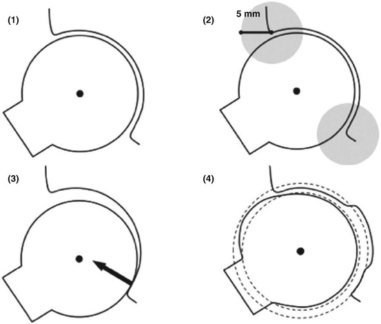
Fig. 3.4
This schematic drawing of the femur and acetabulum explains the different hip joint simulation methods: (1) The Simple Method with a fixed, determined center of rotation, detecting any kind of impingement; (2) The Constrained Method with a 5-mm detection perimeter for impingement at the acetabular rim; (3) The Translated Method with an additional translation vector perpendicular to any detected intra-articular impingement area; and (4) The Equidistant Method with a computed acetabular and femoral sphere, maintaining a dynamic center of rotation and equidistant joint space. Reproduced from Puls et al. [29] with permission from Taylor & Francis, Inc.
A2 Surgical
This system is the only one currently available for clinical use with software that includes the complex anatomical parameters on both the femoral and acetabular morphology and dynamically determines all potential sources of mechanical impingement. The system is unique in that it provides assistance in surgical decision making of whether an arthroscopic, open, or combined approach is necessary to address the present pathology. This software also allows the surgeon to predict the specific location of impingement with dynamic maneuvers of the hip. Lastly, the system provides insight on the amount of resection required to eliminate impingement and achieve a target improvement in hip kinematics and motion.
High-resolution CT imaging is incorporated into the system and the software subsequently calculates and determines the center of the femoral head. A 3D model of the femur is generated and the neck-shaft angle and anteversion is determined along with a 3D map of the head-neck junction [35]. A 3D model of the pelvis and acetabulum is also generated. Virtual digital fluoroscopic images are also generated allowing the surgeon to match with the preoperative radiographs with intraoperative fluoroscopic image to correct for pelvic tilt or rotation. The 3D model will correspondingly adjust with the fluoroscopic image to reflect these changes in tilt and obliquity. The target alpha angle for the cam osteochondroplasty is then template to restore desired femoral head sphericity. The software then determines the region of asphericity and generates a topographic map of the cam lesion. The peak zone of loss of offset is also defined along the clockface of the head-neck junction and is of significant utility in defining the optimal intraoperative fluoroscopic position necessary to identify and resect bone at the location of maximum deformity. The volume of the necessary resection is also defined. The desired correction on the acetabular rim can also be template. The system has the ability to generate a predictive virtual fluoroscopic image that demonstrates changes that occur post-correction of the femur and acetabulum. This feature is of great utility intraoperatively in correlating the template resection with anticipated changes in radiographic landmarks.
Related posts:
 Computational Image-Guided Technologies in Cranio-Maxillofacial Soft Tissue Planning and Simulation
 Introduction to Surgical Navigation
 Virtual Cranio-Maxillofacial Surgery Planning with Stereo Graphics and Haptics
 Spinal Loading System: A Novel Technique for Assessing Spinal Flexibility in Adolescent Idiopathic Scoliosis
 Navigation in Spinal Surgery
 3D Projection-Based Navigation
Stay updated, free articles. Join our Telegram channel

Full access? Get Clinical Tree


