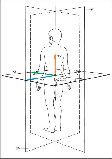
3 Biomechanical Principles of the Spine and Joints A well-founded understanding of spinal biomechanics is helpful in the clinical and radiographic assessment and treatment of the spine and the limbs. This chapter is based on the fundamental work by White and Panjabi (1978, 1990) and Panjabi (2003). It places particular emphasis on those biomechanical principles that are particularly relevant clinically in the assessment of the various neuromusculo-skeletal (NMSK) disorders. Types of motion and the barrier concepts as related to the clinical practice of manual medicine have been described in the previous chapter. Any movement in space can be defined within the framework of a three-dimensional coordinate system. Derived from general principles in the field of mechanical engineering, this system has also found general acceptance and application in biomechanics, ensuring precise description and definition of body movement or individual parts in space. The three-dimensional coordinate is based on the three fundamental component axes constructed perpendicular to each other. By convention, the human body in its neutral, anatomic position is placed in space, with the anteroposterior view being the standard examination view (Fig. 3.1). The point of intersection (0-point) of the three axes is hypothetically placed between the sacral horns. By convention, a set of three reference arrows is arranged such that they point in the positive direction, whereas arrows pointing in the opposite direction are, again by convention, designated as negative. The three primary axes are defined as follows (Figs. 3.1, 3.2, 3.3): • The transverse (horizontal) x -axis. The direction to the left from the center point is designated as +x, whereas the direction to the right is designated as − x. • The vertical y -axis, which is perpendicular to the x -axis. The superior direction is designated as +y, while the inferior direction is designated as −y. • The sagittal z-axis, which is perpendicular to the x -axis in the horizontal plane. The anterior direction is designated as +z, whereas the posterior direction is designated as −z. Fig. 3.1 Three-dimensional coordinate system.
General Biomechanical Principles
Clinical Biomechanics of the Spine
The Axial System
yz | Sagittal plane |
xz | Horizontal plane |
xy | Frontal plane |
The combination of any two of the three axes defines one of the three major planes in this coordinate system (Fig. 3.1):
• The sagittal plane is formed by the y– and z-axes.
• The horizontal plane is formed by the x– and z-axes.
• The frontal plane is defined by the x– and y-axes.
This system then allows one to analyze any spinal motion in general, or a particular vertebral motion segment in terms of rotation about a particular axis, or motion with reference to or within a particular plane, or as a combination of different axes or planes.
In regard to axial rotation, clockwise rotation is designated as the positive (+) direction, whereas counter-clockwise rotation is designated as the negative (−) direction.
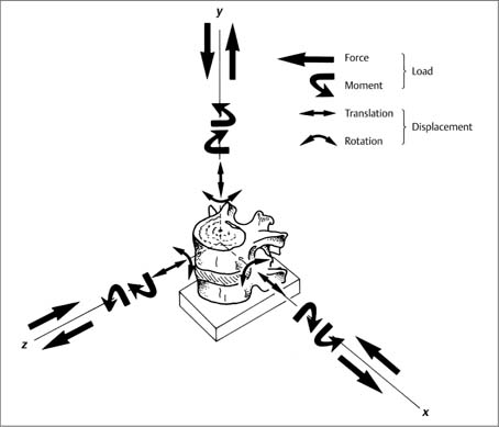
Fig. 3.2 A three-dimensional coordinate system has been placed at the center of the upper vertebral body of a vertebral unit (motion segment). An applied force (compression or distraction) or a rotary moment (along an axis either clockwise or counterclockwise) substitute a loading force that will result in displacement of a vertebra. A total of 12 load components, that is either linear or rotatory forces or moments, can act on theses axes; the application of any one of the load components (linear or rotatory) produces displacement of the upper vertebra with respect to the lower vertebra. This displacement consists of translation and rotation. With permission from White and Panjabi, Clinical Biomechanics of the Spine, Lippincott Williams & Wilkins, 1990.
• Flexion (+øx) describes positive rotation around the x- axis in the sagittal plane.
• Extension (−øx) describes negative rotation around the x-axis in the sagittal plane.
• Side-bending (lateral bending) to the right (+øz): positive rotation around the z-axis in the frontal plane.
• Side-bending (lateral bending) to the left (−øz): negative rotation around the z-axis in the frontal plane.
• Axial rotation (+øy), positive rotation to the left around the y-axis in the horizontal plane.
• Axial rotation (−øy), negative rotation to the right around the y-axis in the horizontal plane.
Using this convention, it is possible to break down the more complex movements into individual uniformly defined movement components. In other words, any movement can be described as a function of a rotational movement around a particular axis. Clockwise rotation is designated as +ø, and the counterclockwise rotation is designated as −ø (Fig. 3.3).
Side-bending movement to the right is described as rotation +øz, while side-bending to the left corresponds to the description of −øz. Forward flexion motion in the sagittal plane corresponds to +øx, and spinal extension is denoted by −øx. Axial rotation to the left is described by +øy, whereas rotation to the right corresponds to −øy.
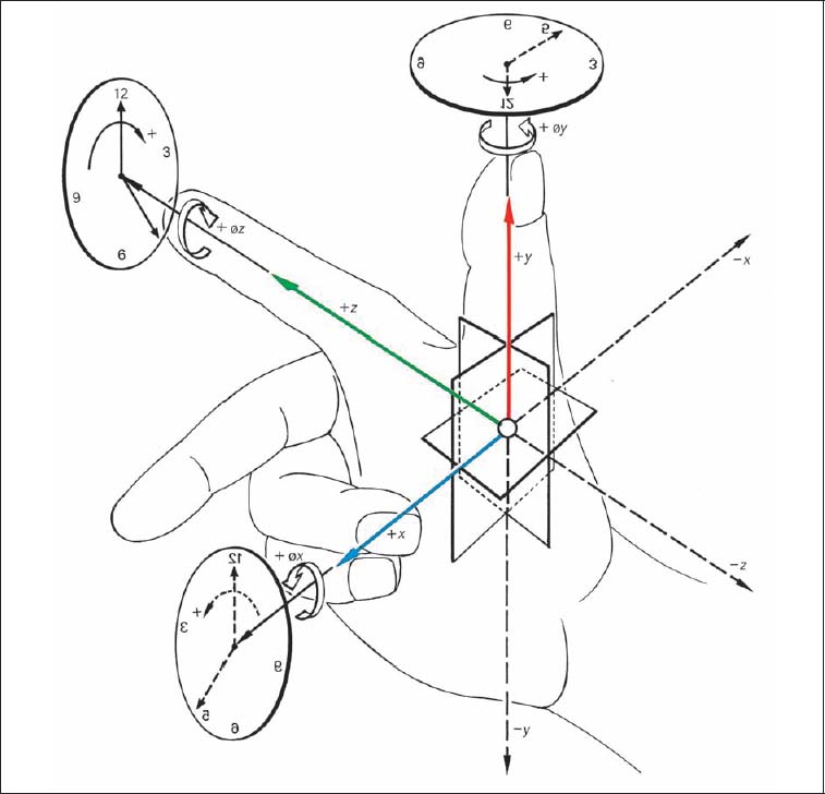
Fig. 3.3 Three-finger model applied to the three-dimensional coordinate system.
Other Motion Description Conventions
In recent years, additional conventions have been introduced to further assist in establishing a “common language” for the description of both gross spinal motion and individual segmental movement:
• Vertebral rotation around a particular axis is defined in reference to the superior or the anterior portion of the particular vertebra (Fig. 3.4). For example, axial rotation of the vertebra to the left (+øy) denotes that the anterior aspect of the vertebral body moves to the left direction.
• Motion between two adjacent vertebrae (the two partners of a spinal segment, also called the vertebral motion unit or motion segment) is described by convention as movement of the superior partner of the two vertebrae in relationship to its inferior vertebral partner.
• Degrees of freedom: Each spinal facet joint has six degrees of freedom. This is in contrast to the six motion directions just described above (flexion–extension, side-bending left and right, axial rotation left and right). Each degree of freedom, based on motion in relation to a particular axis, is defined in terms of: (a) motion about/around one axis (rotation); and (b) motion along an axis (translatory motion).
Although individual physiologic movement components should, in theory, be amenable to a well-defined analysis using the descriptive mathematical–mechanical model, it should always be remembered that the vertebral column is both anatomically and functionally a rather complex system that simultaneously has to fulfill dual roles—namely, assuring sufficient stability while at the same time allowing sufficient motion.
Movement in the individual spinal segments is a combination of translatory and rotatory movements around a particular axis as defined by the three-dimensional coordinate system (refer to Fig. 3.2).
Coupled Motions
Axial rotation (±øy) and side-bending (±øz) in a spinal segment usually do not take place in a single motion direction in a “pure” plane type of motion, as these two movement directions are coupled to each other. This linkage has become known as coupling patterns (Lysell, 1969; White and Panjabi, 1978, 1990; Stoobey, 1967).
The individual coupled motions are governed by the architecture of the vertebrae (smooth, rough, etc.), their joint surface inclination, the associated ligaments, and the interactive functioning of the paraspinal muscles. The physiologic anteroposterior curvature of the spine in the sagittal plane is of great significance as well.
Biomechanics of the Upper Cervical Spinal Joints (CO–C1–C2)
Atlanto-Occipital Joint (CO–C1)
The articulation between the skull and the atlas is formed by two paired structures, each of which consists of the occipital condyle and the superior facet of the atlas. The articulating surfaces are oval, resembling a beanlike configuration. The upper surface of the condyles is convex, while the surface of the superior facet of the atlas is concave. In the adult, the sagittal axial angle of the joints measures between 50° and 60° (Ingelmark, 1947; Bernhard, 1976) (Fig. 3.5).
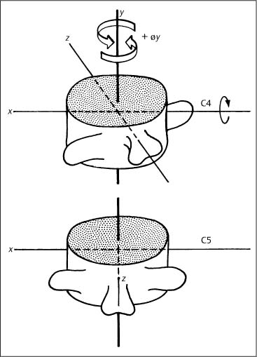
Fig. 3.4 Definition of rotation movement.
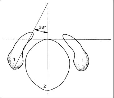
Fig. 3.5 Sagittal angle of the joint axes for the occipital condyles (after Ingelmark, 1947).
1 Occipital condyles
2 Foramen magnum
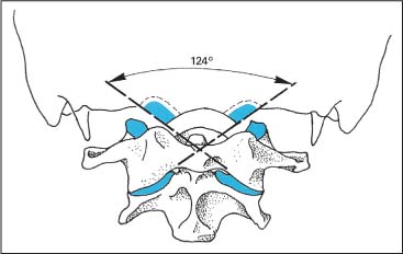
Fig. 3.6 Frontal angle of the joint axes for the occipital condyles (after Stoff, 1976a) is 124° for men, 127° for women (blue: articulating surface).
The frontal axial angle of the joints (Fig. 3.6) resultsfrom lines drawn parallel to the articulating surfaces of the condyles. On the average, it measures 124.2° (Stoff, 1976). This axial angle is increased in the presence of condylar hypoplasia and basilar impression.
Von Lanz and Wachsmuth (1979) describe the joint between the occiput and the atlas as a modified spherical articulation, with motion taking place around two axes according to the anatomic arrangement. The left and right joints actually appear to function with greater motion around the transverse axis than the sagittal axis.
Flexion and extension movements take place around the transverse axis, whereas side-bending is around the sagittal axis (Fig. 3.7).
Function of the Upper Cervical Spinal Joints (CO–C1)
At the atlantoaxial articulation, rotation takes place around the transverse axis, measuring an average of 24°. It is limited by the bony and surrounding soft-tissue structures (Panjabi et al. 1988; White and Panjabi 1990) (Table 3.1). Rotation about the transverse at this spinal level has been specifically termed inclination and reclination motion, analogous to forward flexion and extension, respectively.
Cervical spine flexion takes place in two stages (Dul, 1982; Arlen, 1977; Gutmann, 1981). During the first stage, only a positive rotation around the x -axis in the CO–C1 spinal segment has been observed. This forward movement of the head in relation to the atlas is approximately 8°, which has also been assigned the specific term of nutation motion (“nodding”). The spinal segments below this point remain in the neutral position.
It is not until the second phase that rotation (+øx) takes place in the remaining cervical spinal segments below C0–C1: C1–C2 is tilted forward; C2–C3 to C6–C7 undergo flexion. The axis rotates 45° with respect to C7.
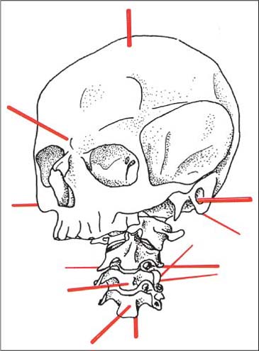
Fig. 3.7 Axes of motion of the occipito-atlanto-axial and cervical joints. (After Knese, 1947.)
Flexion (Inclination) | Extension (Reclination) |
Nuchal ligament | Bony structures |
Alar ligaments | Anterior neck muscles |
Posterior longitudinal ligament | Anterior longitudinal ligament |
Longitudinal fascicle of the cruciform ligament |
|
Tectorical membrane | Alar ligaments |
Posterior neck muscles | Anterior longitudinal ligament |
Ligamentum flavum (restrains hyperflexion) |
|
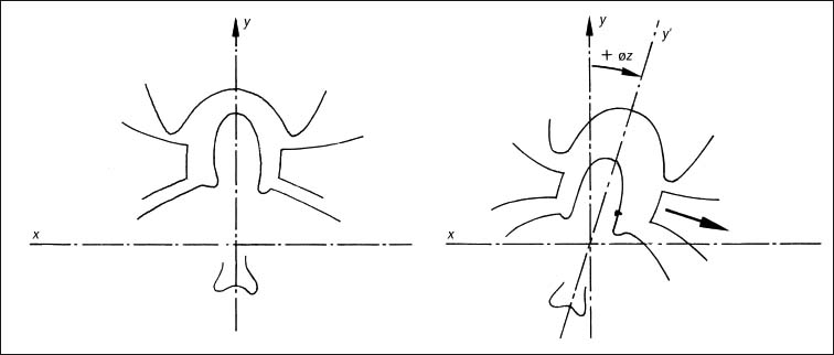
Fig. 3.8 Gliding movement of the atlas with side-bending to the right.
Furthermore, during this second phase a positional change occurs in the CO–C1 segment at the same time as the head rotates backward (in relation to the atlas). This relative negative rotation of the head with reference to the atlas and the axis (i. e., backward rotation) prevents excessive cervical spine extension (e. g., avoiding an abnormal kyphotic component) thus preventing potentially adverse position of the spinal canal.
Side-bending, also commonly referred to as lateral bending, takes place around the sagittal axis and amounts to approximately 5° to either side (Panjabi et al., 1988; White and Panjabi, 1990; Penning 1976). It is greatest when the head is slightly flexed and is reduced due to the function of the alar ligaments.
With side-bending, Gutmann (1981) reports a transverse gliding movement of the atlas between the condyles and the body of the axis (in the atlanto-occipital and atlantoaxial articulation). The gliding movement occurs in the same direction as the gross side-bending movement (Fig. 3.8).
Reports published in the literature that have investigated the biomechanics of side-bending movement at C0–C1 have also not been consistent. Pure cervical spine side-bending motion without simultaneous rotation of the head would indeed represent a rather biomechanically complex movement. In addition to segmental tilting, there is always forced coupled rotation in the same direction as that of side-bending in the C2–C7 vertebrae. Starting at the superior end of the cervical spine, the degree of this forced rotational movement decreases in the inferior direction. Werne (1957) and Fielding (1957) report that with maximal side-bending the axis actually rotates to a greater degree than during maximal rotation of the head and cervical spine. Lewit’s (1986) findings vary from those reported by Werne and Fielding, while Gutmann (1985) and Kamieth (1987) emphasize that there is virtually no atlas rotation with pure side-bending movement.
Various mechanisms have been proposed to explain the cause of this forced rotation. Most authors agree that it is due to the unique anatomic architecture of these articulations in the cervical spine.
Werne (1957) suggests that the forced rotation of the axis is the result of the eccentric insertion of the alar ligaments. Jirout (1973) postulates that, in addition to the influence of the articular processes, the muscles in the head and neck region with their insertions at the spinous processes play a specific role in achieving forced rotation during the second phase.
In the atlantoaxial joint, in addition to axial rotation, there is displacement of the atlas in the same direction as side-bending (in the frontal plane). This becomes apparent on the anteroposterior radiographic view, where the dens of the axis is located asymmetrically, on either side of the center between the two lateral masses. The offset is termed positive when the surface of the atlas projects beyond the surface of the axis, and is negative when the surface of the axis projects beyond that of the atlas. Furthermore, the appearance and degree of offset are dependent upon the changes stemming from the rotation of the axis itself. According to Gutmann (1985) and Lewit (1986), it is the wedgelike anatomic arrangement of the atlas that causes it to be displaced toward the side of lateral bending.
Reports about the lateral displacement of the atlas have been equally inconsistent. Keim (1953) found that with maximal side-bending, lateral atlas displacement occurred in all of the 25 cases studied. Lewit (1986), studying a group of 30 healthy persons, found in four cases a paradoxical lateral atlas displacement; that is, where the atlas was displaced toward the side opposite to that of lateral bending. In both of these studies, the side-bending motion was introduced actively by the study participants.
Jirout (1973) found that atlantoaxial movements are more pronounced during passive than during active side-bending motion. Kamieth (1986) postulates that the displacement is due to induced or forced motion at the axis.
We hypothesize that the lateral atlas displacement may actually result from engaging the anterior portion of the alar ligament as it wraps itself around the dens. Assuming the course of the alar ligaments follows that described by Ludwig (1952), our hypothesis for the lateral atlas displacement also postulates that the lateral displacement is secondary to the forced rotation of the axis (Fig. 3.9).
In all of the 30 adolescents studied by one of the authors (Reich and Dvořák, 1986a,b) the gliding movement of the atlas occurred in the same direction as the induced side-bending motion. This gliding movement became even more pronounced in patients with demonstrated atlantoaxial instability secondary to rheumatoid arthritis. The distance between the dens of the axis and the lateral mass of the atlas was used for measurement.
Not surprisingly, reports about the rotation movement in the atlantoaxial joint are also not consistent. Fielding (Fielding, 1957; Fielding and Hawkins, 1978), White and Panjabi (1978), and Penning (1968) reported that rotation in this joint is nonexistent, whereas Depreux and Mestdagh (1974) described approximately 5° of motion, with values being significantly higher in persons who had undergone atlantoaxial fusion.
Gutmann (1981) reports that when the head is turned, both the head and atlas rotate simultaneously (±ø y) with respect to the axis. The lateral portion of the fibrous joint capsule associated with the facet joints in the upper cervical spine is taut, allowing for particular control of rotation and side-bending, in conjunction with the other limiting anatomic factors, namely, that of facet joint inclination. Caviezel (1976) clinically utilizes a so-called “springing test” to assess passive rotation at the extreme of operator-induced rotation.
Using functional computed tomography (CT) scans of the upper cervical spine in fresh cadavers, rotation between the occiput and the atlas was unequivocally demonstrated (Dvořák and Hayek, 1986) with reported mean values of 4.5° and 5.9° for rotation to the right and to the left, respectively. In healthy adults, rotation between the occiput and the atlas was also clearly demonstrated via functional CT scans, with an average value of 4° (Dvořák and Hayek, 1987).
The in-vitro studies by Panjabi et al. (1988) and Crisco et al. (1991) utilized stereophotogrammetry to evaluate the three-dimensional motion patterns in the upper cervical spine. It was found that the atlanto-occipital rotation measures 7° to either side. Table 3.2 summarizes the mean range of motion values at the atlanto-occipital articulation as presented by various investigators.
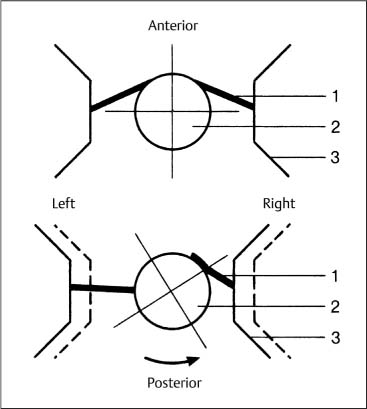
Fig. 3.9 Atlas displacement with side-bending; hypothetical mechanism. Coupled rotation of the axis causes the anterior portion of the right alar ligament to be wrapped around the dens, thus bringing the right-sided lateral mass of the atlas closer to the dens. The anterior portion of the left alar ligament does not become tight until its insertion has been rotated into the posterior position. (After Werne, 1957.)
1 Alar ligament
2 Dens of the axis
3 Atlas (lateral mass)
Atlantoaxial Joint (C1–C2)
The atlantoaxial articulations are of great clinical significance in the field of manual medicine. Here, motion takes place within four articular spaces, one of which is designated as the atlantodental bursa and is represented by the space between the transverse ligament of the atlas and the dens of the axis.
The medial atlantoaxial joint is located between the dens of the axis and the posterior surface of the anterior arch of the atlas. The two articular spaces of the lateral atlantoaxial joint are of particular importance (Fig. 3.10).
The joint surfaces are usually round, but sometimes triangular, and are covered with cartilage that is 1.4 to 3.2 mm thick. The articular surfaces of the axis are convex, and those of the atlas are relatively flat, causing an anterior and posterior gap of 2–5 mm (Knese, 1947) (Fig. 3.11).
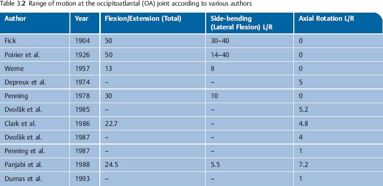
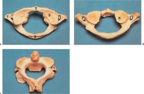
Fig. 3.10
a Atlas, superior view; the superior joint surfaces are oval, sometimes with double formation (right).
b Atlas, view from inferior; round joint surfaces.
c Axis, superior view; the joint surfaces point inferiorly (convex).
1 Transverse process
2 Anterior tubercle
3 Superior articular facet of the atlas
4 Transverse foramen
5 Posterior tubercle
6 Inferior articular facet of the atlas
7 Spinous process
The joint capsule is wide and flabby, and from the medial wall a cuneiform synovial fold invaginates into the articular space, which is described as meniscoid (Dvořák and Aebi, 1987).
Function of the Atlantoaxial Joint
Flexion and Extension
The bony structures of the articular surfaces and the motion-limiting ligaments allow movement around the transverse axis that can be as large as 10° and 15° (Figs. 3.10, 3.11). Using lateral radiographic projections, the effectiveness of the ligaments can be determined by measuring the distance between the posterior portion of the anterior arch of the atlas and the dens of the axis.
Side-bending
Side-bending between C1 and C2 is only possible with simultaneous rotation around the axis. This is described as forced rotation and is thought to be the result of the physiologic function of the alar ligaments. Lewit (1970) and Jirout (1973) report displacement of the atlas in the same direction as that of the forced induced side-bending.
Axial Rotation
The head and atlas rotate simultaneously on the axis around the dens. The axis of rotation passes through the dens of the axis and is clinically “secured” by the transverse ligament of the atlas (Fig. 3.12). Average rotation in the young, healthy adult is 43° (SD = 6°), which amounts to approximately half of the total cervical spine rotation (Dvořák and Hayek 1987).
Normal values for axial rotation in the upper cervical spine are listed in Table 3.3.
Cinematographic studies by Fielding (1957, 1978) clearly demonstrate that, starting with the head in the anatomically neutral position, head and cervical spine rotation occurs first in the atlantoaxial joints. Once their motion is completed, the lower cervical spine segments can begin to rotate. The limitation of the rotation is primarily determined by the alar ligaments (Figs. 3.13, 3.14).
Coupled Movement
• Motion between segments is primarily a coupling between that in the frontal plane (±ø z) and the transverse plane (±ø y). This may occur in either two or three dimensions. According to Gutmann (1981), axial rotation of the head (±ø y) and atlas rotation in the opposite direction occur with side-bending, while C2 undergoes axial rotation toward the same side as in side-bending.
• Translatory gliding: Minimal lateral translatory gliding of up to 2–3 mm takes place in the sagittal plane (z-axis) and the transverse plane (x-axis) (Hohl, 1964). These two movements are always coupled to axial rotation movement. Axial rotation is accompanied by a vertical translatory gliding movement (y-axis). The literature relating to the motion of the atlantoaxial joint is summarized in Table 3.3.
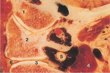
Fig. 3.11 Paramedian sagittal section of the upper cervical spine.
1 Occipital condyle
2 Atlas
3 Axis
4 Vertebral artery
5 Great occipital nerve
6 Meniscoid
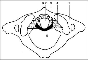
Fig. 3.12 Schematic representation of the ligamentous apparatus at the craniocervical junction.
1 Atlas
2 Dens of the axis
3 Atlantal portion of the alar ligament
4 Occipital portion of the alar ligament
5 Transverse ligament of the atlas
6 Anterior atlantodental ligament
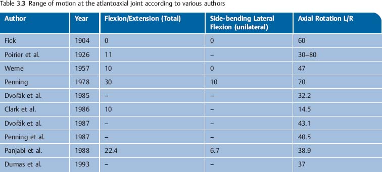
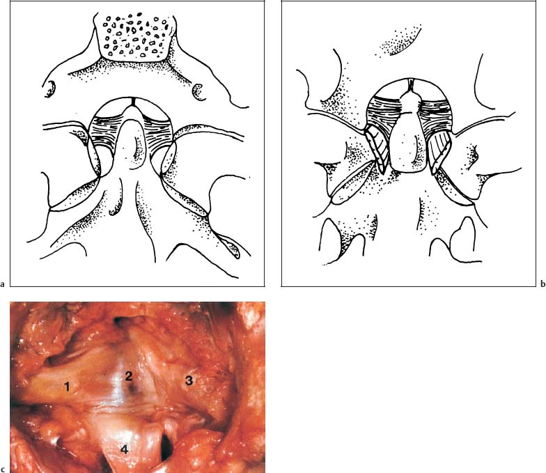
Fig. 3.13a–c The alar ligaments, seen (a) from superior and (b) from anterior. (After Ludwig, 1952.) c Anatomic specimen in the anteroposterior view. 1 Left alar ligament 2 Dens of the axis 3 Right alar ligament 4 Longitudinal ligament
Ligaments of the Upper Cervical Spine (C0–C1 and C1–C2)
The ligaments that are of particular interest with regard to the function of the atlanto-occipital and atlantoaxial joints are the alar ligaments and the cruciform ligament of the atlas (Fig. 3.12).
Alar Ligaments
Ludwig (1952) describes the alar ligament as an irregular, quadrilateral pyramid-like trunk. The rectangular base lies against the superior two-thirds of the lateral surface of the dens. The superior, posterior, and anterior surfaces connect the dens with the occipital condyle, while the inferior and lateral surfaces connect the dens with the lateral mass of the atlas (Fig. 3.13).
The orientation of the fibers in the sagittal plane is primarily a function of the height difference between the tip of the dens of the axis and the occipital condyles (Fig. 3.13). The ligament that connects the dens of the axis with the anterior arch of the atlas is part of the alar ligament as well (Fig. 3.14). Occasionally, the presence of another ligamentous connection between the base of the dens of the axis and the anterior arch of the atlas has been reported, and has been referred to as the anterior atlantodental ligament.
Biomechanics of the Alar Ligaments
The mechanical properties of the alar ligaments depend primarily on three factors:
• Fiber orientation.
• The proportion of collagenous versus elastic fibers.
• The mechanical properties of the collagenous and elastic fibers.
The collagenous fibers will be irreversibly stretched if subjected to a stretch beyond 6–8% of their resting length, and will ultimately start to tear when stretched beyond that limit (Abrahams, 1967). Elastic fibers, in contrast, can be stretched to 200% of their resting length, beyond which, however, they will rupture abruptly. It can thus be said that in essence the collagenous fibers do not undergo any perceptible stretch.
The alar ligaments are made up almost entirely of collagenous fibers (Fig. 3.15). At their attachments they run parallel, while at the center they tend to be interdigitated in a criss–cross pattern (Dvořák et al., 1988a). Saldinger et al. (1990) report that the alar ligaments begin to tear at 200 newtons.
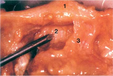
Fig. 3.14 Ligamentous interconnection between the dens of the axis and the atlas. View from superior onto the ligaments associated with the upper cervical spinal joints. The probe is on the anterior atlantodental ligament.
1 Anterior arch of the atlas
2 Anterior atlantodental ligament
3 Alar ligament
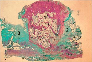
Fig. 3.15 The alar ligaments are made up of collagenous fibers (Giemsa stain).
1 Dens axis
2 Left alar ligament
3 Right alar ligament
Function of the Alar Ligaments
The function of the alar ligaments can be straightforwardly inferred from their course by following them from their attachment at the occipital condyles to that at the atlas. The primary role of the alar ligaments is to limit axial rotation in the upper cervical spine, particularly at the CO–C1 and C1–C2 articulations. Rotation to the right is limited by the left alar ligament and, conversely, rotation to the left is limited by the right alar ligament. Rotation to one side causes the contralateral ligament to become more taut (Fig. 3.16). During side-bending motion toward one side (= rotation around the z-axis), the occipital portion of the ipsilateral ligament is relaxed whereas the atlas portion becomes taut. This mechanism then limits the gliding motion of the atlas in the same direction as the induced side-bending movement. At the same time, the occipital portion of the opposite alar ligament becomes tighter, which limits gliding of the occipital condyles in the opposite direction (Fig. 3.17).
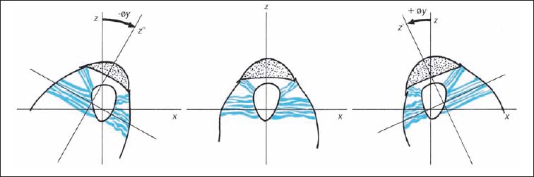
Fig. 3.16 Function of the alar ligaments during rotation in the atlantoaxial joint (C1–C2).
z–z′ | Rotation to the right | y–y′ | Side-bending to the right |
z–z″ | Rotation to the left | y–y″ | Side-Bending to the left |
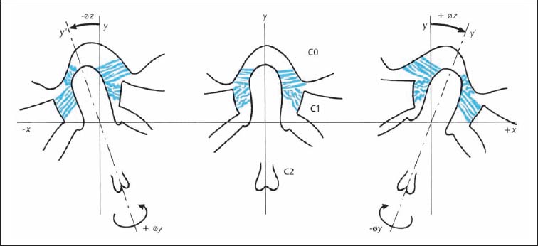
Fig. 3.17 Function of the alar ligaments during side-bending in the atlantoaxial joint (C1–C1).
The tight occipital portion of the alar ligament with its posterior and eccentric origin at the dens of the axis, together with the atlantal portion and its anterior eccentric origin at the dens, induces forced rotation of the axis in the same direction as the side of induced side-bending. Clinically, and according to the convention of motion description using the anterior portion of the vertebral body as the reference, the spinous process of the axis moves oppositely to the induced side-bending. In other words, it moves in the same direction as the convexity (Fig. 3.17) (Reich and Dvořák, 1986; Dvořák and Panjabi, 1987b). Despite a number of experimental studies, it cannot be conclusively stated whether the alar ligaments are alone responsible for the described forced rotation of the axis. This is especially true since the joint architecture and in particular the surface inclination, may play an inherent role. More studies are necessary to clarify the complex function of the alar ligaments.
Flexion in the upper cervical spine is chiefly limited by the nuchal ligaments, the posterior longitudinal ligaments, the tectorial membrane and the longitudinal fascicles of the cruciform ligament. Increasing tension in the alar ligaments as the spine gradually moves toward the extreme of flexion also participates in the limitation of flexion (Panjabi et al., 1991).
The alar ligaments are subject to great tension forces and are therefore more likely to be irreversibly stretched or may ultimately rupture. This is especially true in a situation where the head is rotated maximally (rotation around the y-axis) followed by flexion and extension movements (rotation around the x -axis). A similar position has been observed in people involved in rear-end motor vehicle collisions. It can therefore be surmised that under similar circumstances it is the alar ligaments that are subject to damage, whereas the transverse ligament might remain unaffected.
During rotation motion of the atlantoaxial joint, the alar ligament on the opposite side is stretched and “rolled up” around the dens of the axis; the alar ligament on the same side relaxes. Thus, during rotation to the right, the left alar ligament is wrapped around the dens while the right ligament is relaxed (Figs. 3.9, 3.16).
During side-bending motion, the ipsilateral alar ligament relaxes, and the stretched ligament of the opposite side causes a forced rotation of the axis in the direction of the bending, due to its attachment to the dens of the axis. In the clinical examination, the spinous process of the axis rotates contralaterally (Fig. 3.17). Thus, the strong alar ligaments are able to limit the rotation motion of the atlantoaxial articulation (Panjabi et al., 1991).
The Cruciform Ligament of the Atlas
The cruciform ligament consists of two differently directed components: the horizontal transverse ligament of the atlas and the vertical longitudinal fasciculi (Fig. 3.18). The transverse ligament of the atlas arises from the medial surfaces of the lateral masses of the atlas, while some fibers also attach to the tip of the dens. In its central portion, the cruciform ligament is approximately 10 mm high and 2 mm thick and is covered by a thin layer of cartilage. The longitudinal fascicles are comparatively weak and are present inconsistently. They merge with the atlanto-occipital membrane (Saldinger et al., 1990).
Biomechanics of the Transverse Ligament of the Atlas
The transverse ligament of the atlas consists primarily of collagen fibers that may become irreversibly stretched when subject to excess tension (Kennedy et al., 1976). The collagenous fiber bundles are oriented in parallel at the insertion only to form a criss–cross pattern at the center of the ligament, which is also the thickest portion. The portion facing the dens of the axis may reveal fibrocartilagenous changes.
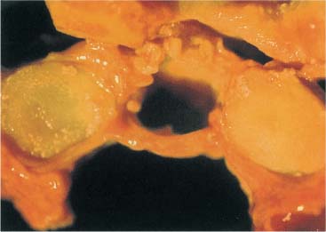
Fig. 3.18 Prepared specimen at the transverse ligament of the atlas between the articular process of the atlas.
Function of the Cruciform Ligament of the Atlas
The function of the cruciform ligament is to regulate and limit physiologic rotation between C1 and C2 and to protect the spinal cord form the dens of the axis.
Injury to the Ligaments Associated with the Upper Cervical Spine (C0–C1, C1–C2)
The transverse ligament of the axis ruptures at approximately 350 N. Histologic examinations reveal that the primary site of rupture is at the bone–cartilage insertion interface (Saldinger et al., 1990).
Macalister (1893) found that the transverse ligament of the atlas tears at a load of 1275 N (130 kg). Fielding et al. (1974) examined the tensile strength of the alar ligaments and the cruciform ligament of the atlas in 20 corpses. They found that theses ligaments tear at a load of 400 N to 1800 N (average, 1100 N).
The transverse ligament of the atlas tears when stretched beyond a length between 4.8 and 7.6 mm. Over-stretching will lead to tearing of the collagenous fibers, which is represented on radiographs as an increase of more than 3 mm between the dens and the posterior surface of the anterior arch of the axis (more prominent in radiographs taken in the flexed position). When there is an increased distance of 7 mm, complete separation of the transverse ligament from the atlas should be suspected, while distances greater than 10–12 mm would be a clear indication of a torn alar ligament.
The spatial relationship between the bony structures of the atlas, the dens of the axis, the spinal cord, and the free zone is designated as an anatomical constant. Generally, the rule of “thirds” due to Steel (1968) has proved valuable (Fig. 3.19). One-third of the space is occupied by the dens, one-third by the spinal cord, and one-third by a free space, the so-called safety zone of the spinal cord.
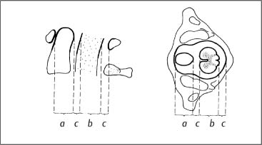
Fig. 3.19 Steel’s rule of thirds (Steel, 1968):
a =b = 2c = ⅓(a + b + 2c)
a = dens axis
b = spinal cord
c = safety zone
Fig. 3.20 Drawing of the uncovertebral joints. (After Luschka, 1858.)
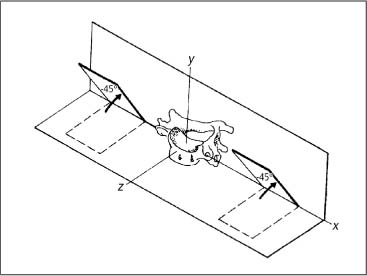
Fig. 3.21 Facet joint inclinations and axes of motion for vertebra C4. (After White and Panjabi, 1978.)
Considering the significance of the anatomic position of the cardiac and respiratory centers in the medulla oblongata, it is plausible to hypothesize that there are not one but two sets of ligaments that assist in the prevention of a dens dislocation, namely, the alar ligaments and the transverse ligament of the axis.
Huguenin (personal communication, 1980) points out the clinical symptomatology and the potential changes seen on radiographs as a result of either partial or complete tears involving the ligaments in the occipito-atlanto-axial joint region, both in functional tomograms and CT scans.
Biomechanics of the Lower Cervical Spine (C3–C7)
The axis represents a transitional vertebra between the upper and lower cervical spine. The greatest range of motion takes place in the mid-cervical spine region with the following possible motion directions: cervical flexion and extension, side-bending (e. g., lateral bending or lateral flexion), and rotation. The vertebral motion units (i. e., spinal segments) inferior to the axis represent the typical cervical vertebrae. They have a similar joint and vertebral body architecture, which aids in the load distribution. In contradistinction to the thoracic and lumbar vertebrae, the cervical vertebrae exhibit the uncinate processes laterally (Fig. 3.20) (Luschka, 1858; Tönduri and Theiler, 1990).
The inclination of the mid- and lower cervical spine facets is approximately 45° with respect to the horizontal plane. The lower segments are sloped more steeply than the upper segments (Fig. 3.21).
Panjabi et al. (1993) describe the three-dimensional anatomy of the apophyseal joints (synonyms: zygapophyseal joints or facet joints). In the cervical spine, the vertebra with the largest joint surface is the axis (C2: 200 mm2); the next largest are C3 through C5 (101–107 mm2), and C6 and C7 show the smallest joint surfaces (79mm2
Related posts:
 Evidence Base in Manual Medicine for the Treatment of Back Pain Syndromes: Background, Status, and Practice
 The Pharmacologic and Psychologic Treatment of Chronic Pain
 Nonradicular Pain: Spondylogenic and Myofascial Pain Syndromes
 Myofascial Trigger Point Treatment
 Structural and Functional Diagnosis and Treatment of the Spine, Ribs, Pelvis, and Sacroiliac Joint
 Structural Diagnosis and Functional Treatment of the Limbs
Stay updated, free articles. Join our Telegram channel

Full access? Get Clinical Tree


