Basic Science of Metals
Jeremy L. Gilbert
Orthopedic Alloys
The history of arthroplasty and the use of orthopedic alloys has been reviewed by Dowson (1) and by Friedman et al. (2). In the early 1920s and 1930s, interpositional arthroplasty was investigated; with this technique, a material was interposed between the two sides of the joint to inhibit arthrodesis. A variety of materials were considered for this application. The metals investigated consisted of gold foil and a cobalt-chromium-molybdenum (Co-Cr-Mo) alloy (Vitallium, Howmedica, Inc.), which was then in use as a dental material. Use of steels in fracture fixation was reported as early as 1804 (2). Stainless steel (18% chromium, 8% nickel) was not introduced until 1926. However, its corrosion resistance was not adequate for long-term implantation until it was later found that 2% to 3% molybdenum would reduce pitting and crevice corrosion attack.
The modern age of joint replacement appears to be based, in part, on the work of Wiles, who introduced a stainless steel total joint replacement in 1938 (3). In the 1950s, McKee and Ferrar (4) introduced the first metal-on-metal total joint, initially using stainless steel but later switching to the Co-Cr-Mo alloy (Vitallium). These prostheses were used well into the 1970s. The concept of metal-on-metal articulating surfaces was seeing increased use until recently when tribocorrosion reactions (a combination of wear and corrosion known as mechanically assisted corrosion [MAC]) were seen to dramatically impact the performance and clinical behavior of these devices. These metal-on-metal devices will be discussed in later sections on wear and corrosion.
It is generally accepted that Co-Cr-Mo–based alloys were initially used in dentistry and were adopted later by the orthopedics community. These alloys were developed by E. Haynes in the early 1900s (Haynes Stellite-21). By the 1930s, Vitallium (see Table 15.3 later, for the composition of ASTM F-75) was in use as an alloy for partial dentures (5). These alloys were not developed by the aircraft industry as many have stated; but rather, they were adapted to high-temperature aircraft engine use in 1941. As such, cobalt-based alloys are thought of as superalloys.
Titanium alloys were developed primarily for the aircraft industry and were adopted by the biomaterials community in the late 1950s and early 1960s. In recent years, they have come to be among the most heavily used alloys in orthopedics for several reasons, including their high strength, low modulus, and excellent corrosion resistance.
The alloys used today in orthopedic applications primarily include iron-based (stainless steel), cobalt-based, and titanium-based alloys. Recently, other alloys including zirconium (Zr) and tantalum alloys have gained in use. In total joint replacements, the primary alloy systems used are the Co-Cr-Mo and titanium alloys, in particular, titanium, 6 aluminum, 4 vanadium (Ti-6 Al-4 V ELI). In some regions of the world, stainless steel prostheses are utilized (e.g., United Kingdom) with newer formulations of these alloys coming into use. Each of these alloys has a particular set of physical and mechanical properties that make them highly successful in orthopedic applications.
This chapter reviews the basic science of orthopedic alloys, and identifies the bulk and surface structures, and the properties that result in the highly successful materials in use today. It will also touch upon the basic mechanisms of degradation in orthopedic alloys, including corrosion, wear, and fatigue. Alternative surface treatments to enhance the surface properties of alloys (wear and corrosion resistance) are reviewed, and clinical findings related to alloy degradation discussed. Moreover, some future possibilities for alloys and surface treatments are presented.
Basic Science of Metals
As is true for any class of materials, the properties and performance of metals and alloys are dependent on the composition and structure of the material. In a classic materials science sense, processing–structure–property relationships will dictate metal behavior. That is, how a material is fabricated will affect the resulting structure (e.g., grain size, alloy composition, carbide distribution), and, subsequently, these structural features will dictate, to a large extent, the resultant mechanical and physical properties (e.g., fatigue strength and corrosion resistance). If one can gain an appreciation of these structure–property relationships, then one will be in a better position to assess alternative materials or treatments.
Atomic Structure and Defects
Metals are made up of crystals. That is, metal atoms are positioned in a three-dimensional periodic array within a
single crystal. A typical implant is composed of many metal crystals (i.e., it is polycrystalline) joined together at grain boundaries (Fig. 15.1). Many of the physical and mechanical properties of metals are governed by these crystals. There are several different possible relationships between atoms within a crystal (i.e., its crystal structure). These include body-centered cubic (BCC), face-centered cubic (FCC), and hexagonal close-packed (HCP) (Fig. 15.2). There are 14 different ways atoms can be arrayed in a crystal (the so-called Bravais lattices (6)). However, most of the implant alloys used in orthopedics are either BCC (e.g., β-Ti), FCC (e.g., 316L stainless steel), or HCP (e.g., α-Ti, Co-Cr).
single crystal. A typical implant is composed of many metal crystals (i.e., it is polycrystalline) joined together at grain boundaries (Fig. 15.1). Many of the physical and mechanical properties of metals are governed by these crystals. There are several different possible relationships between atoms within a crystal (i.e., its crystal structure). These include body-centered cubic (BCC), face-centered cubic (FCC), and hexagonal close-packed (HCP) (Fig. 15.2). There are 14 different ways atoms can be arrayed in a crystal (the so-called Bravais lattices (6)). However, most of the implant alloys used in orthopedics are either BCC (e.g., β-Ti), FCC (e.g., 316L stainless steel), or HCP (e.g., α-Ti, Co-Cr).
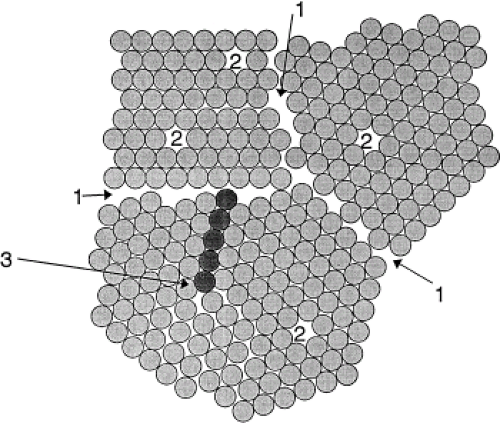 |
It is important to note that metal crystals are not defect free. In fact, there are several types of defects in metals that, it turns out, are the primary factors affecting properties. These defects can be classified according to their spatial dimension (i.e., point defect, line defect, area defect, and volume defect).
Point defects are known as vacancies. These defects occur when a lattice site in the crystal is not occupied by a metal atom (see Fig. 15.1). These defects are present in all metals and alloys and provide a mechanism for diffusion in solids.
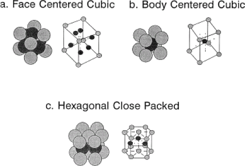 Figure 15.2. Three common crystal structures found in implant alloys: face-centered cubic (FCC) (A), body-centered cubic (BCC) (B), and hexagonal close-packed (HCP) (C) crystal structures. |
Line defects, also known as dislocations, are the major defect affecting the mechanical properties of metals. A dislocation is the result of an extra half-plane of atoms in a crystal (see Fig. 15.1). That is, when a plane of atoms terminates within the middle of the crystal, it locally distorts the crystal structure. This distortion or internal strain energy is experienced only in the immediate vicinity of the end of the extra half-plane of atoms; therefore, a dislocation is a line defect where the line represents the end of the half-plane. When a stress of sufficient magnitude is applied, these dislocations can move through the lattice, resulting in a permanent change in the shape of the crystal, and the metal is said to plastically deform. When a metal is deformed plastically (i.e., there is a permanent deformation that remains after the loading is removed), the cause was the creation and movement of dislocations.
Grain boundaries can be thought of as area defects. That is, the region where two metal crystals come together is the grain boundary (see Fig. 15.1), and it is a region of higher disorder in the metal than the internal grain regions.
Finally, volume defects, known as voids or cracks, are well-known and more easily understood forms of defects, which can impact on the mechanical performance of a metal or alloy. Even small scratches on the surface of a metal may significantly affect the behavior of the alloy (e.g., lower the fatigue strength). Grain boundaries are also where second-phase particles like carbides can form and these particles are also factors in the properties of alloys both in terms of bulk properties (e.g., strength, ductility) and surface properties (e.g., wear resistance, corrosion behavior, etc.)
Each of these forms of defects can have a profound effect on the behavior of the alloy. In particular, the mechanical behaviors of the alloy (e.g., its strength, ductility, fracture toughness, fatigue resistance) are all dependent on how the structure of the alloy affects its deformation mechanisms (primarily dislocation generation and motion). In fact, the key to understanding how and why metals and alloys are strengthened is based on an understanding of dislocations. Those processes or structures within the polycrystalline metal that tend to impede the motion of dislocations will act to strengthen the metal. There are other deformation mechanisms possible in metal alloy systems, including twinning and grain boundary sliding. These alternative deformation mechanisms are not as prevalent (typically) as dislocation motion and will not be discussed here.
Strengthening Mechanisms in Orthopedic Alloys
Orthopedic alloys rely on several different mechanisms for improvements in strength. These strengthening mechanisms are based on the concept of impeding dislocation motion. That is, if there are methods (such as alloying, heat treating, or cold working) that make it more difficult for dislocations to move, then alloys that have undergone these processes will be stronger. The following is a brief description of the most common strengthening mechanisms.
Solid Solution Strengthening
Solid solution strengthening, both interstitial and substitutional, results when one or more elements (the so-called solute) are added to the primary metal (the so-called solvent metal) to form an alloy (a mixture of two or more elements). The solute atoms can reside in one of two possible sites within the lattice, either substituting for a solvent atom on a lattice site or sitting in an interstitial site between solvent atoms (see Fig. 15.1). Substitutional atoms are typically of a size similar to that of the solvent, whereas interstitial atoms are typically much smaller (e.g., C, O, N, or B). Both interstitial and substitutional atoms contribute to the strength of a metal. However, interstitial atoms are typically more effective. For example, the addition of less than 0.1% carbon to iron results in a steel with about a 10-fold increase in strength. Similarly, in titanium, the addition of small amounts of oxygen (an interstitial solute atom) will significantly increase strength. Solid solution strengthening can result in several modifications of microstructure that will affect strength. The main effect is to pin dislocations by developing locally solute-rich regions in the vicinity of the dislocation line. These so-called dislocation atmospheres increase the strain energy needed to break the dislocation free and move it (i.e., induce plastic deformation), thus raising the strength of the alloy.
Cold and Hot Working
Cold working is a process whereby deformation of a metal results in an increase in strength. On a microstructural level, deformation of the metal or alloy results in a significant increase in the dislocation density (the amount of dislocation line per unit volume) and entangles these dislocations into tight bundles. This results in a structure in which it is much more difficult to continue to move dislocations within the lattice. Thus, the strength can increase substantially as a result of cold working. Cold working typically increases both yield strength and ultimate strength, but it decreases ductility. Cold working is often performed on 316L stainless steel as a strengthening mechanism. The metal may be cold worked by rolling, compression between two platens, drawing through a die (for wire and rod), or another deformation mechanism.
To remove some or most of the dislocations created during cold working, a heat-treatment process called annealing is performed. In this process, the alloy is heated to a sufficiently high temperature (but below any transformation temperature), and, over a period of time, new grains of dislocation-free material will nucleate and grow into the previously cold-worked grains. This process is called recrystallization, and it causes the alloy to return to its precold-worked structure and properties. Other processes also take place during heating of cold-worked alloys. These include a process called “recovery” and another called “grain growth.” Both have some effect on mechanical properties but not to the extent that recrystallization does. Annealing is performed for several possible reasons, including to restore the ductility of the material, relieve internal (or residual) stresses, and reduce the grain size of the material (see later).
Very often, alloys are hot worked (deformed at a high temperature). These high-temperature deformation processes fall into the category of thermomechanical processes. Wrought (deformed into shape) and forged (high-temperature deformation to form a shape) are both terms describing thermomechanical processes. Often, high-temperature deformation processes are performed to form a shape (i.e., a hip prosthesis), but these processes can also alter the microstructure of the alloy. For example, in the ASTM standard for Ti-6 Al-4 V (ASTM F-136, ASTM F-1481), a “bi-modal” α + β microstructure is called for. This microstructure results from the deformation of Ti-6 Al-4 V at a temperature high in the α + β phase region, but still below the β transus temperature (about 930°C).
Grain size reduction can also be attained during hot working. In this process, the deformation of the grains increases the internal strain energy by the generation and entanglement of dislocations. This strain energy can be eliminated by a process known as recrystallization described above, during which new grains that are relatively dislocation-free nucleate and grow into the old, heavily deformed grains. Depending on the temperature, time, and extent of prior deformation, the grain size of the structure can be refined by this process. See one of several good references on this subject (7).
Grain Size Effects
Grain size affects the strength of an alloy. This, again, is the result of the interaction of the grain boundaries with the dislocations in the grains. Grain boundaries prevent dislocations from easily passing from one grain to another. Thus, they impede dislocation motion. If there are more grain boundaries per unit volume (which results when grains are smaller), then it will be more difficult to move dislocations (i.e., to plastically deform). Therefore, increases in strength can be obtained if one makes smaller grains (assuming no other process intervenes). Newer Co-Cr-Mo alloys in use utilize this approach by way of powder metallurgy techniques where fine micron-size powders of alloy are made which are then packed together under high temperature to form a solid metal part. This approach preserves the small size of each individual grain (or powder particle) but combines them together into a larger piece for manufacture of implant components.
Precipitation Hardening
Precipitation hardening is a mechanism that relies on the presence of a second phase dispersed in the parent microstructure to inhibit dislocation motion. This mechanism can operate only in those materials in which second-phase particles or grains can exist. Examples of where precipitation hardening can occur are in Co-Cr-Mo alloys and in Ti-6 Al-4 V. Typically, metal carbides can form in Co-Cr-Mo alloys, and, if these carbides are uniformly dispersed through the structure, they can pin dislocations and make it more difficult to deform. Variations in the size and distribution of precipitates within the structure will alter the mechanical properties. Precipitates will grow over time when the alloy is subjected to high temperatures, as in an annealing or homogenization
treatment. When precipitation-strengthened alloys are heated, this process is called aging. There is typically an optimal aging treatment for an alloy, which represents an optimal distribution of precipitates through the structure.
treatment. When precipitation-strengthened alloys are heated, this process is called aging. There is typically an optimal aging treatment for an alloy, which represents an optimal distribution of precipitates through the structure.
It should be pointed out that orthopedic implants are manufactured in several ways, including casting (for cobalt-based prostheses), machining from forged or wrought bar stock, and forging into near-net shape. Cast Co-Cr-Mo alloy prostheses may have large variations in grain size as well as very large grains, up to 2 to 5 mm in diameter. Large grain sizes and variability can reduce strength; therefore, cast Co-Cr-Mo microstructures are typically lower in strength than fine-grained wrought Co-Cr-Mo microstructures (see Table 15.4 for examples).
Other manufacturing processes include hot isostatic pressing (HIP’ing) or powders. Here, the alloy is first made into fine powders (on the micron scale) by spraying droplets of molten alloy into a chamber and letting the drops solidify. Once collected, these fine powders are placed in a shaped mould and heater and pressed to allow sintering or diffusion bonding and consolidation to take place. This is done by heating and pressing adjacent powder beads so that atoms on the surface can interdiffuse and bond together. HIP’ing is also used to attach porous surface coating on to prostheses. Other surface-coating methods can include plasma spraying metal, or hydroxyapatite, precipitation of calcium phosphates from solution, or other surface coatings.
Mechanical Properties
When discussing strengthening mechanisms in metals, it is important to understand what is meant (or not meant) by strength. Figure 15.3 is a typical stress–strain curve for a metal. In it are defined the terms used to describe the mechanical behavior of a metal (or other material). In the low-stress/low-strain region, there is typically a linear relationship between stress and strain. This proportionality is known as the modulus, Young’s modulus, or elastic modulus. This property reflects the stiffness of the material, which is dependent on the ease or difficulty of stretching atoms from their equilibrium position in the crystal lattice. Modulus is relatively insensitive to the presence of defects such as dislocations.
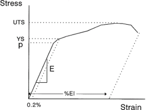 Figure 15.3. Schematic stress–strain curve for a typical metal. Note the elastic region with Young’s modulus (E), proportional limit (P), yield strength (YS), ultimate tensile strength (UTS), and percent elongation (%El). |
The stiffness of a prosthesis is the result of a combination of geometry and modulus. For hip stems, the main deformation mode is bending and the stiffness concept for beam bending is known as the flexural rigidity (EI), where I is known as the second moment of area and is a measure of the spread of the cross-sectional area about its center axis. This concept is exploited in some hip stems by, for example, reducing the flexural rigidity by putting a slot in the distal stem shaft. This effectively lowers the distal stem rigidity and allows for less stress shielding to occur.
Returning to the tensile test curve of Figure 15.3, as the stress increases beyond the elastic range, there is a point at which dislocations begin to be created and to move through the grains and impart some plastic deformation. When this occurs, there is no longer a linear relationship between stress and strain. The material is said to reach the proportional limit. When the permanent deformation reaches 0.2%, the stress at this arbitrary permanent strain defines the yield stress of the material. The ultimate stress of the material is the highest stress reached during testing; the percent elongation is the amount of plastic strain imparted prior to failure and is a measure of the ductility of the material. Other measures of ductility include the reduction of area, which is the percent change in the cross-sectional area in a tensile sample before testing and after failure.
There are other material properties that are important to consider for implant applications. A primary mechanical property of interest to total joint replacements is the fatigue strength. Fatigue is a process whereby a cyclic stress or strain is applied to a material and, over the course of many cycles (up to 107 cycles or more), a crack is initiated and propagated to failure. Most people load their hips on average 2 to 5 million times per year, clearly a high-cycle fatigue condition. Fatigue Strength of a material is the cyclic stress required to cause failure at some number of cycles. Fatigue Life is another term often used to describe fatigue behavior. The fatigue life of a material is the number of cycles to cause failure at a fixed cyclic stress. These two terms are related to each other in a classic cyclic-stress-versus-number-of-cycles-to-failure curve (also known as a Wohler curve, or an S-N curve). This is a plot of the cyclic stress versus the log of the number of cycles to failure (Fig. 15.4). As a general rule, the fatigue strength of an implant alloy will scale with the
tensile strength of the alloy. For example, for high-cycle/low-stress fatigue situations, the fatigue strength (at 107 cycles) is about 0.3 to 0.5 of the ultimate tensile strength (UTS) (8). High-cycle fatigue is when the number of cycles required to cause failure is about 104 or greater. In metals, during high-cycle fatigue, most of the fatigue life is spent initiating a fatigue crack, and only a small percentage is spent propagating that crack to failure. Thus, those material properties that will inhibit crack initiation will be more successful in enhancing the fatigue life of the material. These include creating smooth surfaces since fatigue cracks tend to initiate at the surface, imparting compressive residual stresses at the surface (e.g., ion implantation), and raising the cold work level, or hardness, of the surface (e.g., shot peening or ion implantation.)
tensile strength of the alloy. For example, for high-cycle/low-stress fatigue situations, the fatigue strength (at 107 cycles) is about 0.3 to 0.5 of the ultimate tensile strength (UTS) (8). High-cycle fatigue is when the number of cycles required to cause failure is about 104 or greater. In metals, during high-cycle fatigue, most of the fatigue life is spent initiating a fatigue crack, and only a small percentage is spent propagating that crack to failure. Thus, those material properties that will inhibit crack initiation will be more successful in enhancing the fatigue life of the material. These include creating smooth surfaces since fatigue cracks tend to initiate at the surface, imparting compressive residual stresses at the surface (e.g., ion implantation), and raising the cold work level, or hardness, of the surface (e.g., shot peening or ion implantation.)
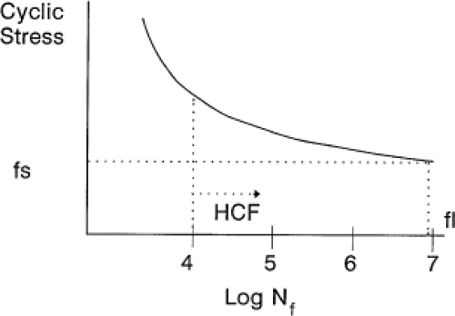 Figure 15.4. Schematic of a fatigue curve. Wohler diagram: cyclic stress versus log number of cycles-to-failure curve (S-N curve) for fatigue evaluation; fs, fatigue strength at 107 cycles; fl, fatigue life at fs; HCP, high-cycle fatigue regime. |
Specific Implant Alloys
Stainless Steels
Stainless steels are iron-carbon–based alloys and are covered by ASTM specifications F-138, F-139, F-621, F-745, F-899, F-1314, F-1586, and F-2229 (9,10,11,12,13,14). In general, these alloys contain, by weight, approximately 18% to 22% Cr, 12% to 14% Ni, 2.5% Mo, 2% to 5% Mn, and 0.03% to 0.08% C (Table 15.1). The steels described in ASTM F-899 are for use as surgical instruments rather than surgical implants and include both 300 series (austenitic) and 400 series (martensitic) steels. The latter steels are heat-treatable steels (i.e., they will vary their mechanical properties with different heat treatment procedures), whereas 300 series steels (e.g., 316) are not heat treatable but can be cold worked.
The most common steels used for implants (e.g., bone plates, screws) are the 316 stainless steels, which are austenitic (i.e., they have an FCC crystal structure). There are two grades, grade 1 (316) and grade 2 (316L), with the L designating a lower carbon content. Other alloys include a nitrogen-strengthened, manganese-containing alloy (ASTM F-1314). An example of the microstructure of stainless steel is shown in the scanning electron micrograph (SEM) in Figure 15.5. Newer steel alloys include F-2229, which has a lower Ni content and tends to be more pitting corrosion resistant than standard 316L stainless steel.
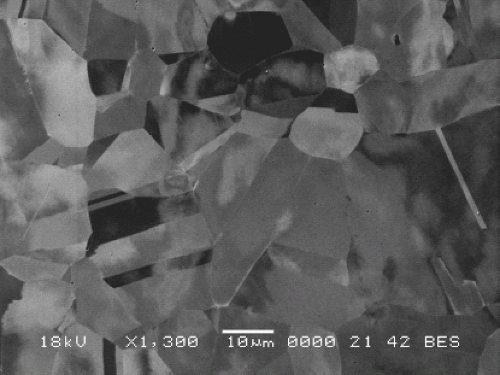 Figure 15.5. Backscattered electron image (BEI) of a 316L stainless steel alloy that has been electropolished. Backscattered electrons provide contrast in the image as a result of crystallographic orientation differences between grains. (Backscattered electron imaging is also known as electron-channeling contrast imaging.) Note that the grains also show evidence of twins, which are structures in the grains that result from deformation. |
Table 15.1 Chemical Composition of Most Used Iron-based Alloys | |||||||||||||||||||||||||||||||||||||||||||||||||||||||||||||||||||||||||||||
|---|---|---|---|---|---|---|---|---|---|---|---|---|---|---|---|---|---|---|---|---|---|---|---|---|---|---|---|---|---|---|---|---|---|---|---|---|---|---|---|---|---|---|---|---|---|---|---|---|---|---|---|---|---|---|---|---|---|---|---|---|---|---|---|---|---|---|---|---|---|---|---|---|---|---|---|---|---|
| |||||||||||||||||||||||||||||||||||||||||||||||||||||||||||||||||||||||||||||
The austenitic (316 series) alloys are typically used in fracture-fixation devices, such as bone plates, intramedullary rods, and bone screws. They have been used for total joint replacements in the past, and are seeing increased use in Europe (particularly the United Kingdom). In the past, they were found to be less reliable than the current alloys used in these applications (cobalt-based and titanium-based alloys) although newer steel alloys appear to be much more capable of withstanding the loading and environment of the body. They are solid solution strengthened and can be cold (or hot) worked to increase strength. Hot working can also be performed to reduce the grain size of the material. They are not typically precipitation strengthened, with the exception of F-1314, which may contain small dispersions of carbonitrides within the grains. The low-carbon content in grade 2 was meant to minimize the potential for forming metal carbides, the presence of which may adversely affect the corrosion resistance of the alloy by a process known as sensitization (15). The mechanical properties of the steel alloys used in orthopedics are listed in Table 15.2.
Table 15.2 Mechanical Properties of Stainless Steels | ||||||||||||||||||||
|---|---|---|---|---|---|---|---|---|---|---|---|---|---|---|---|---|---|---|---|---|
| ||||||||||||||||||||
Cobalt-Based Alloys
The cobalt-based alloys typically contain chromium, molybdenum, carbon, and other elements such as nickel, silicon, and iron. Table 15.3 summarizes the ASTM-designated cobalt-based alloys used in medical devices. Cobalt-based alloys in use today include ASTM F-75, F-90, F-562, F-563, F-688, F-799, F-1058, F-1091, F-1377, and F-1537 (16,17,18,19,20,21,22,23,24,25). Some of these specifications have compositions similar to others, or they do not address alloy composition. The only difference between F-1537 and F-75 is the presence of a higher nitrogen concentration in the former. Cobalt alloys can be either an FCC (α) structure (typically at temperatures higher than 400°C) or an HCP (ε) structure (T lower than 400°C) (26).
Cobalt-based alloys are used primarily in total joint replacement applications where high strength and corrosion resistance are necessary. These alloys are strengthened by solid-solution strengthening and, to some extent, precipitation hardening resulting from the precipitation of carbides. A typical microstructure of a cast Co-Cr-Mo hip prosthesis is shown in cross section in the optical micrograph in Figure 15.6. Note the very large grains present as a result of the casting, as well as the smaller grains near the porous coating on the surface. Also shown in this micrograph are the dispersed carbides present within the grains (and at the grain boundaries), which provide some precipitation strengthening. The as-cast structure of Co-Cr-Mo is one of a dendritic (treelike) structure with a highly varying chemistry across the dendrite (called coring) (27,28


Related posts:


Stay updated, free articles. Join our Telegram channel
Full access? Get Clinical Tree
