Augmented Lateral Ankle Ligament Reconstruction for Persistent Ankle Instability
Patient Selection
Indications

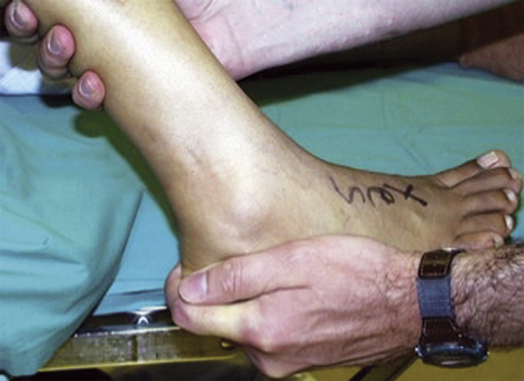
Figure 1Photograph shows the anterior drawer test. The foot is slightly plantarflexed and internally rotated. The examiner’s right hand stabilizes the tibia while the left hand exerts an anterior pull.
In the United States, 27,000 ankle ligament sprains occur daily
Most are treated nonsurgically if seen in acute period
Even chronic injuries should have trial of physical therapy
Persistent pain, giving way, locking, swelling are reasons for further evaluation
Osteochondral defects, spurs, and tibiotalar arthritis may develop with persistent instability
Symptoms of more than 10 years, hyperlaxity, and irreparable ligaments intraoperatively, failed broström procedure may need tendon or fibertape augmentation as opposed to native ligament reconstruction
Physical examination shows anterior translation with anterior drawer test (Figure 1)
Contraindications
Arthritis
Inability to participate in postoperative therapy
Posterior tibial tendon insufficiency
Neuropathic/Charcot arthropathy of the foot
Preoperative Imaging
Stress radiographs are no longer recommended
Weight-bearing radiographs are used to determine articular space and alignment
Varus tibiotalar joint—May need more than just soft-tissue reconstruction, including supramalleolar osteotomy
Varus heel alignment—May need lateralizing calcaneal osteotomy in addition to ligament reconstruction
Plantarflexed first ray—May increase varus moment of hindfoot and require dorsiflexion osteotomy during ligament reconstruction
MRI can identify injury to anterior talofibular ligament (ATFL) and calcaneofibular ligament (CFL)
Procedure
Room Setup/Patient Positioning

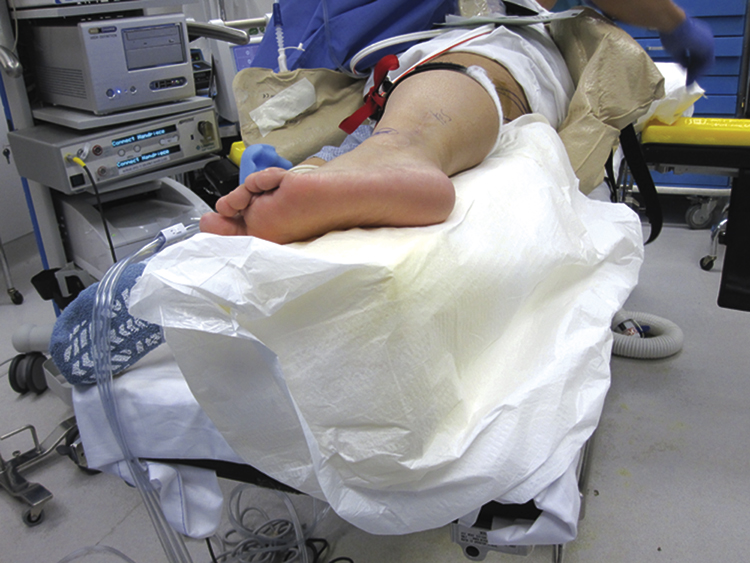
Figure 2Photograph shows setup and patient positioning for lateral ankle ligament reconstruction. The surgical leg is elevated on a foam block. The peroneal nerve of the nonsurgical leg and all bony prominences are shielded from any pressure.
Semilateral position on beanbag, with affected leg up (Figure 2)
Ensure external rotation of leg to allow placement of a medial arthroscopy portal
Regional block for saphenous nerve but popliteal block anesthetic overall
Surgical Technique
| Video 86.1 Augmented Lateral Ankle Ligament Reconstruction. Nicholas A. Abidi, MD; Brian Martin, PA-C (25 min) |


