Fig. 13.1
Mark out anatomy
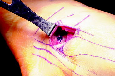
Fig. 13.2
Extensor retinaculum in blue
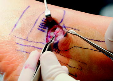
Fig. 13.3
ATFL cut
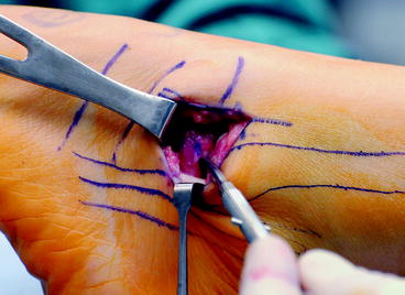
Fig. 13.4
Lateral talocalcaneal
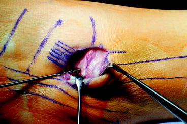
Fig. 13.5
Drill holes in the fibula for CFL tunnel
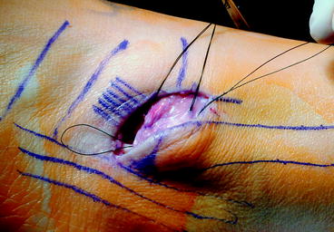
Fig. 13.6
Reinforcement of extensor retinaculum
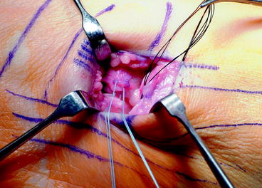
Fig. 13.7
Reconstruction of the LTCL
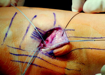
Fig. 13.8
Passage of CFL through drill holes
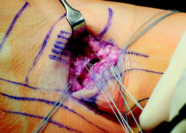
Fig. 13.9
LTCL at 8 o’clock; ATFL, CFL suture at 2 o’clock
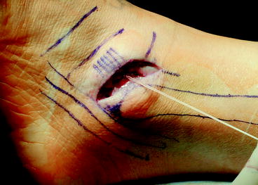
Fig. 13.10
Extensor retinaculum with 2.0 Vicryl
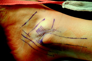
Fig. 13.11
The anterior lateral incision can have a very cosmetic closure
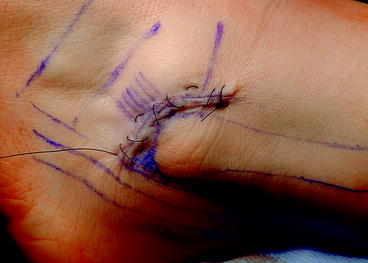
Fig. 13.12
Tulane two step
Tendon augmented ligament reconstruction can be done using gracilis or semi-tendinosis autograft or allograft. This is generally reserved for failed initial Broström reconstruction or primary reconstruction in patients with generalized ligamentous laxity. Tunnels are created in the fibula to allow for passage of a tubularized graft, with a typical graft measuring between 5 and 6 mm in diameter. Careful attention must be made to create tunnels that do not break the most distal portion of the fibula, as subsequent fixation can be quite difficult. Tunnels are placed at the insertion of the ATFL on the talus and CFL on the calcaneus (Figs. 13.13 and 13.14). Fixation is maintained with interference screws with the foot held in slight valgus position (Fig. 13.15).
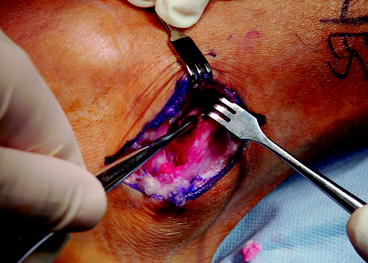
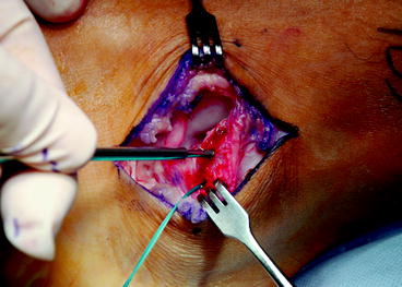
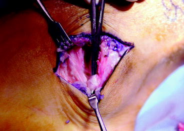
Fig. 13.13
Curette the bottom of the fibula for CFL attachment
Fig. 13.14
Suture anchors can be used for CFL attachment
Fig. 13.15
The CFL is identified approximately 90–110° relative to the ATFL
13.4.2 Nonanatomic Tenodesis
Watson-Jones described the first of these procedures in 1952. He described a procedure where the peroneus brevis was woven through the calcaneus and fibula. Evans later simplified this procedure by placing the distally attached brevis through an oblique drill hole in the distal fibula and tenodesed this to the brevis stump.
The Chrisman–Snook procedure24 performed through a curved incision over the course of the peroneal tendons from the myotendinous junction to the base of the fifth metatarsal. The sural nerve should be identified prior to dividing the ligament maintaining the peroneal tendons in their groove. Next the peroneus longus is retracted to expose the peroneus brevis in the groove. The brevis is split longitudinally from its insertion, leaving the attachment to the base of the fifth metatarsal intact. Then the half with the longest tendon component is divided at the myotendinous junction. At this point, an appropriately sized drill hole is made in the anteroposterior direction at or just proximal to the level of the tibiotalar joint, with the graft placed from anterior to posterior. With the foot in neutral with mild eversion, the graft is tensioned and sutured to the periosteal/ligamentous tissues adjacent to the anterior drill hole, reconstructing the ATFL. At this point, the peroneus longus and the remaining brevis are returned to their groove. The split tendon passes over their superficial border to help prevent dislocation. The surface of the calcaneus is then exposed and two drill holes are made 1.5 cm apart at the same diameter as the distal fibular holes. These are connected using curettes. The tendon is passed from posterior to anterior, with sutures at both ends of the tunnel. The remaining tendon is then attached to the anterior portion of the graft either near the base of the fifth metatarsal or at the anterior fibular drill hole.
13.5 Postoperative Protocols and Results
Generally, after any of these procedures, the patient is placed in a short leg splint or cast and made non-weight bearing for a period of 2 weeks. Following this, weight bearing is allowed in a cast. At 6 weeks after surgery, the patient is allowed to begin proprioceptive and strength training.
The results of the Broström–Gould procedure have been repeatedly good to excellent. Several studies examining the results find 91% excellent results at 2.6-year follow-up,25 or 87% good-to-excellent results.26 However, these authors note that failure of previous surgeries, generalized ligamentous laxity, and instability of greater than 10 years were relative contraindications. The Watson-Jones procedure yields good to excellent results at 10–18-year follow-up, despite the 18% complication rate (which excludes wound complications).27
Long-term results of the modified Evans procedure are not as favorable with one study showing that only 52% of patients had returned to pre-injury level of activity at 4.6 years after surgery.28 Karlsson found that 50% of patients had unsatisfactory results with 14-year follow-up after the Evans procedure.1
13.6 Syndesmotic Instability
Syndesmotic injuries or “high ankle sprains” most commonly result from rotational injuries or forced abduction. They are seen with lesser frequency with inversion. The incidence of syndesmotic injuries is estimated 1–18% of all ankle injuries.29,30 These injuries are not common, but misdiagnosed or undiagnosed injuries can lead to a chronic pain and disability. The syndesmosis is defined as the anterior inferior tibiofibular ligament (AITFL), the posterior inferior tibiofibular ligament (PITFL), the transverse tibiofibular ligament, and the interosseous membrane and ligament. The AITFL spans from Chaput’s tubercle on the anterior tibia to the anterior distal fibula, with an average width of 20 mm. The interosseous ligament lies 0.5–2 mm above the tibiotalar joint and blends with the interosseous membrane. The PITFL lies on the posterior aspect of the tibia, Volkmann’s tubercle, and inserts on the posterior portion of the distal fibula. The transverse tibiofibular ligament lies just superior and anterior to the PITFL and functions as a labrum. Together these ligaments function to provide stability to the ankle joint. The ankle allows a small degree of excursion of the fibula with normal ankle function. However, if two of these ligamentous structures are injured, there may be significant mechanical laxity.31
13.6.1 Clinical and Radiographic Evaluation
A detailed history, including the interval from injury to presentation, is taken. Common complaints include a sensation of giving way and difficulty walking on uneven ground. A focused clinical examination begins with inspection and palpation for tenderness. They also commonly have stiffness, particularly in dorsiflexion. The “squeeze test” is performed by squeezing the fibula at the level of the mid-calf.32 While suggestive of injury, this test is not sensitive or specific enough to make a diagnosis. A more reliable examination is to have the patient sit with the hips and knees flexed at 90°. The examiner then places a gentle external rotation force, and pain is suggestive of a syndesmotic injury.
Radiographs include an AP, lateral and mortise view of the ankle, as well as a stress external rotation mortise view. Special attention should be paid to the following parameters: increased tibiofibular clear space, decreased tibiofibular overlap, and increased medial clear space.
Tibiofibular clear space is defined as the distance between the medial border of the fibula and the lateral border of the posterior tibia as it extends into the incisura fibularis. The measurement is made 1 cm proximal to the plafond and should be less than 6 mm in both the mortise and AP views. Increased tibiofibular clear space is considered the most reliable indicator of instability.33
The tibiofibular overlap is defined as the portion of the lateral malleolus that overlies the anterior tibial tubercle, measured 1 cm proximal to the plafond. In the AP view, this should be greater than 6 mm or 42% of the fibula width. In the mortise view, it should be greater than 1 mm.
The medial clear space, or the distance between the lateral border of the medial malleolus and medial border of the talus, is measured at the level of the talar dome. In the mortise view, this should be less than or equal to the superior clear space. An increase is more indicative of a deltoid injury than of a syndesmotic injury. Other modalities may be useful, such as computed tomography (CT) or magnetic resonance imaging (MRI). CT is able to assess minor syndesmotic diastasis but MRI is more sensitive and specific, especially since it visualizes the ligamentous structures.
13.6.2 Indications and Treatment
Patients that have persistent symptoms after conservative treatment for a syndesmotic sprain, have instability on stress radiographs, or present more than 3 months after injury should be treated with surgery. Standard syndesmotic treatment should be performed with screw or endobutton suture fixation in acute cases of instability. However, for chronic syndesmotic instability, the medial ankle joint should be opened with a medial arthrotomy. Any interposed tissue, which can be as fibrotic as cartilage, should be debrided from the medial gutter to allow reduction of the talus.
Related posts:


Stay updated, free articles. Join our Telegram channel

Full access? Get Clinical Tree


