Alternative Anchors: Hooks and Sublaminar Wires
Tenner J. Guillaume
John E. Lonstein
In patients with progressive scoliosis, whether or not the cause is idiopathic, neuromuscular, congenital, or syndromic, the goals of surgery are to prevent the spinal deformity from having a long-term adverse effect on patient health-related quality of life. The aim of spinal fusion surgery is restoration of spinal balance, establishment of a solid fusion, and prevention of future curve progression. In order to effect these goals, surgeons use instrumentation in order to bring about curve correction as well as spinal stability to facilitate bony union. Segmental instrumentation is the gold standard in spinal fusion surgery. However, there are many methods by which to achieve segmental fixation. Probably the most commonly used form of segmental fixation is transpedicular screw-based fixation as that initially described by Roy-Camille (4). Nevertheless, the first form of multisegmental fixation described in the literature for the treatment of scoliosis was that of sublaminar wire fixation by Eduardo Luque (5). Though less frequently utilized today, there remains a significant role for sublaminar fixation techniques (wires or tapes) in modern spine surgery. Furthermore, Cotrel and Dubousset described the use of multisegmental hooks in scoliosis in order to achieve segmental fixation to the spine. These are generally laminar hooks, which can be placed on a lamina or transverse process, or pedicle hooks, which can be placed on pedicles. In general, hooks are used today when a surgeon encounters pedicles that appear too small for transpedicular fixation, at the cranial extent of constructs, or as additional fixation.
Comparisons of the forces that can be resisted by different methods of attachment to the vertebra have been performed, and these have demonstrated that sublaminar wires resist only tension, while screws can resist forces acting in all directions except for rotation about their axis, and hooks resist only forces that drive them against the bone surfaces. It is with these biomechanical factors in mind that one can begin to understand the role of each of these alternative anchors in spinal deformity surgery.
The purpose of this chapter is to outline the indications for use of these alternative anchors as well as to act as a step-by-step guide for safe alternative anchor placement.
Indications for the use of alternative anchors include the following:
Scoliosis with thoracic lordosis
Sublaminar tapes or wires
Inability to safely place pedicle screws due to dysplastic or small pedicles
Sublaminar tapes, sublaminar wires, or hooks
Cost considerations
Sublaminar wires
Cranial aspect of instrumentation
Hooks
Hybrid construct
Sublaminar tapes, sublaminar wires, or hooks
Surgeon training or experience
Contraindications to the use of wires include the following:
Absence of or incomplete posterior elements
Myelomeningocele, postlaminectomy, congenital scoliosis with absent posterior elements
An anticipated high-likelihood of implant removal
Wires are difficult to remove due to intracanal adhesions that can occur.
A relative contraindication is dural ectasia or a spinal cord syrinx.
Some surgeons have safely placed sublaminar wires in these circumstances.
Note that transverse process hooks can usually be placed T1-T10 even in the absence of lamina.
SUBLAMINAR WIRES AND TAPES
A major risk of sublaminar wires and tapes is injury to the spinal cord and dura. A major downside to sublaminar wires is a risk of neural injury if they need to be removed. That said, sublaminar wires and tapes are wonderful anchors that should be in the armamentarium of all good spinal deformity surgeons.
If we are using stainless steel implants, then it is our practice to use 16-gauge double-stranded wire for our sublaminar fixation (Fig. 45-1). If we are using cobalt-chrome or titanium instrumentation, then it is our practice to use Dacron mesh tapes for sublaminar fixation (Fig. 45-2).
Prior to initiating sublaminar fixation placement, we have a hemostatic matrix (Surgiflo, Floseal) and absorbable gelatin-compressed sponges (Gelfoam, Surgifoam) available. One must also have the operating room staff prepared for the possibility of an incidental durotomy.
Prior to initiating sublaminar fixation placement, we have a hemostatic matrix (Surgiflo, Floseal) and absorbable gelatin-compressed sponges (Gelfoam, Surgifoam) available. One must also have the operating room staff prepared for the possibility of an incidental durotomy.
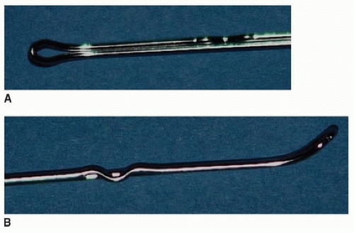 FIGURE 45-1 A 16-gauge looped wire seen from above (A) and from the side (B). |
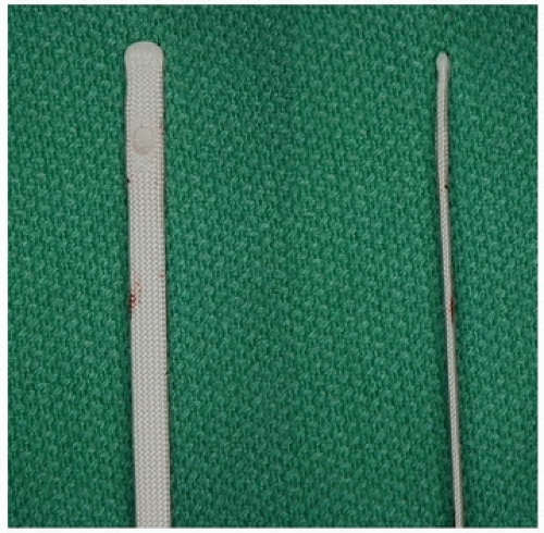 FIGURE 45-2 Sublaminar tape with malleable metal tip. |
The first step in sublaminar fixation is removal of bone overlying the interlaminar space. In the thoracic spine, this requires the removal of spinous processes at each level at which sublaminar fixation is planned as well as the removal of the caudal aspect of the spinous process from the level just cranial to the cranial-most planned sublaminar fixation, though the spinous process of the upper instrumented vertebra (UIV) is preserved to prevent proximal junctional kyphosis (PJK). Oftentimes with lordosis, the removal of the spinous processes alone will not be enough to gain access to the interlaminar ligamentum flavum. Frequently, there can be shingling of the laminae, which requires one to remove the caudal aspect of the cranial lamina at each interspace to be instrumented. This removal can easily be performed in line with the previously performed inferior facetectomies; this results in a chevron-line removal of bone from the lamina. It is our practice to perform removal of the spinous process as well as removal of the caudal lamina at each level with a wide Leksell rongeur. The wide rongeur is preferred as it is very unlikely to plunge into the canal via the interlaminar space, whereas a narrow Leksell rongeur would significantly increase this risk.
After taking down the lamina overlying an interlaminar space, a combination of wide and narrow Leksell rongeurs can be utilized to remove dorsal ligamentum flavum until epidural fat can be seen to be protruding through the midline raphe of the ligamentum flavum, though in case of spinal stenosis or significant lordosis epidural fat may be lacking and the dura may be directly visualized. A Kerrison rongeur is then used to complete the flavectomy using a number 3 or number 4 rongeur. If a Ponte osteotomy is to be performed, then the Kerrison rongeur dissection is carried further laterally to take down the superior articular processes bilaterally in line with the superior margin of the respective pedicle. Once the flavectomy is completed (Fig. 45-3), then passage of the sublaminar wire or tape can occur.
As a reminder, sublaminar wires are made of stainless steel and therefore are usually used with a stainless steel rod construct; if sublaminar tapes are to be utilized, then these can generally be used with different rod materials or sizes. An important step in passing sublaminar wires or tapes is the actual bend applied to the wire. With the tapes, there is a malleable metal embedded within the Dacron mesh tape, which can be contoured for passage, whereas with the sublaminar wires, it is our practice to pass the hairpin-looped end of the wire. In each anchor, an acute, 90-degree bend is made to the terminal 3 mm or so. This allows the tip of the wire or tape to pop up from the interlaminar space as soon as it passes the cranial edge of the lamina. The remainder of the loop or wire is contoured with a smooth arc that will allow passage of the device with minimal encroachment into the spinal canal and that will allow a fluid and smooth passage of the anchor with simple supination of the wrist when the anchor is grasped between the thumb and index fingers. Wires or tapes are ALWAYS passed in a caudal-to-cranial direction around the lamina, except in very unusual circumstances when caudal-to-cranial direction is not successful. One should look at the lamina about which the wire or tape is
to be passed as the implant is being contoured; thoracolumbar lamina tends to be longer in a cranial-to-caudal direction than does the midthoracic lamina. The wire or tape is contoured such that the diameter of the radius of curvature essentially matches the length of the lamina (Figs. 45-4 and 45-5). As such, when the wire or tape is passed, it should “pop up” on the cranial aspect of the lamina as the last portion of the contoured implant passes the caudal aspect of the lamina.
to be passed as the implant is being contoured; thoracolumbar lamina tends to be longer in a cranial-to-caudal direction than does the midthoracic lamina. The wire or tape is contoured such that the diameter of the radius of curvature essentially matches the length of the lamina (Figs. 45-4 and 45-5). As such, when the wire or tape is passed, it should “pop up” on the cranial aspect of the lamina as the last portion of the contoured implant passes the caudal aspect of the lamina.
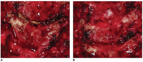 FIGURE 45-3 A. Flavectomy completed caudal to the lamina to be instrumented. B. Flavectomies cranial and caudal to the lamina to be instrumented are completed, a hemostatic matrix like Surgiflo or Floseal can be seen in the interspace cranial to the lamina to be instrumented. Caution—excessive hemostatic matrix in the canal can compromise the spinal cord by mass effect. |
As a wire or tape is passed, it is of utmost importance that contact between the tip of the implant is in constant contact with the ventral portion of the lamina about which it is being passed. If this contact is not maintained, then the wire or tape may be encroaching deep into the canal with high risk of injuring the dorsal aspect of the spinal cord. One of the greatest risks associated with passage of sublaminar fixation is the encroachment that can occur into the spinal canal and the associated
risk of spinal cord contact or contusion. As such, wires and tapes must be passed in a well-controlled manner with careful attention being paid to maintaining the implant as dorsal within the canal as is possible. We recommend the surgeon always maintain posteriorly directed force on the wire or tape while passing it, so it never inadvertently enters the spinal canal deeper than intended.
risk of spinal cord contact or contusion. As such, wires and tapes must be passed in a well-controlled manner with careful attention being paid to maintaining the implant as dorsal within the canal as is possible. We recommend the surgeon always maintain posteriorly directed force on the wire or tape while passing it, so it never inadvertently enters the spinal canal deeper than intended.
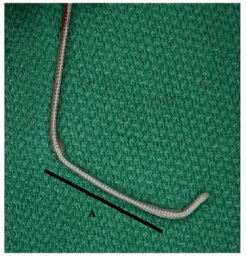 FIGURE 45-4 Contoured bend of sublaminar tape for passage. The length of A should approximately equal the length of the lamina about which the tape is being passed. Note the acute 90-degree bend at the end of the tape, which allows the tape to pop up out of the interspace once it reaches the cranial margin of the lamina about which it is being passed. |
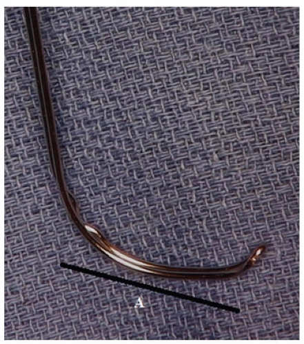 FIGURE 45-5 Contoured bend of sublaminar wire for passage. The length of A should approximately equal the length of the lamina about which the wire is being passed. Note the acute 90-degree bend at the end of the wire, which allows the wire to pop up out of the interspace once it reaches the cranial margin of the lamina about which it is being passed. |
As the wire or tape emerges at the cranial aspect of the lamina, a nerve hook (sublaminar wire) or needle driver (sublaminar wire or tape) is used to gain control of this end of the implant, again with a constant posteriorly directed force. The needle driver is utilized to grab the end of the sublaminar tape; the nerve hook is passed into the hairpin loop of the 16-gauge wire (Figs. 45-6A, B and 45 7A-C). Once control of the cranial aspect of the implant has been achieved, the wire or tape must be passed. In order to maintain the anchor as dorsal within the canal as possible, a posteriorly directed force is applied to both the cranial and caudal portions of the implant pulling the implant against the ventral aspect of the lamina. Initially, the posteriorly directed force is equal on both ends of the implant. As the implant is passed, the forces vary to allow the hand controlling the cranial aspect of the implant to take
on more force than the hand controlling the caudal aspect of the implant. As such, the implant then passes cranially but with well-maintained control and posteriorly directed forces to keep the implant against the ventral aspect of the lamina and within the dorsal spinal canal. In the cases of both wires and tapes, one will generally pass the implant until there are equal lengths both cranial and caudal to the lamina. At this point, the wire is then bent down at an acute angle over the lamina in order to maintain the wire in its dorsal position within the spinal canal and to ensure that any unintentional contact with the wire by the surgeon will not result in canal or spinal cord encroachment (Fig. 45-6C, D). If the wire is not bent over the lamina in this manner, then the surgeon runs a high risk of inadvertent contact with the wire that can plunge into the canal and spinal cord. Flexible tapes are probably less likely to injure the spinal cord in this fashion compared to a stiff wire, with metal cables probably somewhere in between. The looped end of the wire is bent over the cranial aspect of the lamina medially relative to the ball-tipped end of the wire that is bent over the caudal aspect of the lamina laterally. The tapes are connected to their rod-anchoring device, which is design specific (Fig. 45-7D).
on more force than the hand controlling the caudal aspect of the implant. As such, the implant then passes cranially but with well-maintained control and posteriorly directed forces to keep the implant against the ventral aspect of the lamina and within the dorsal spinal canal. In the cases of both wires and tapes, one will generally pass the implant until there are equal lengths both cranial and caudal to the lamina. At this point, the wire is then bent down at an acute angle over the lamina in order to maintain the wire in its dorsal position within the spinal canal and to ensure that any unintentional contact with the wire by the surgeon will not result in canal or spinal cord encroachment (Fig. 45-6C, D). If the wire is not bent over the lamina in this manner, then the surgeon runs a high risk of inadvertent contact with the wire that can plunge into the canal and spinal cord. Flexible tapes are probably less likely to injure the spinal cord in this fashion compared to a stiff wire, with metal cables probably somewhere in between. The looped end of the wire is bent over the cranial aspect of the lamina medially relative to the ball-tipped end of the wire that is bent over the caudal aspect of the lamina laterally. The tapes are connected to their rod-anchoring device, which is design specific (Fig. 45-7D).
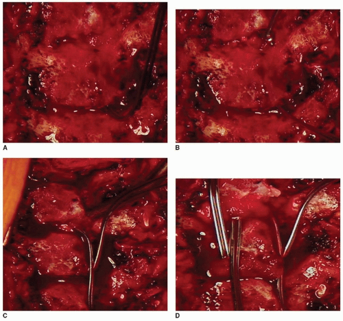 FIGURE 45-6 Sublaminar wire passage begins at the caudal aspect of the lamina (A) and the wire is then passed cranially. When the tip of the wire emerges at the cranial aspect of the lamina, a nerve hook is used to control the hairpin-looped end of the wire and to facilitate wire passage (B). After the wire has been fully passed, it is folded down directly over the lamina to prevent inadvertent entrance into the spinal canal, which could cause permanent spinal cord injury. C. Unilateral. D. Bilateral. |
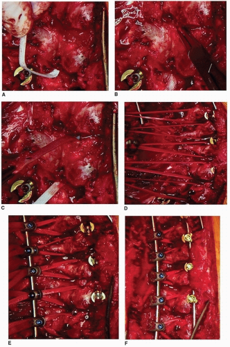 FIGURE 45-7 Sublaminar tapes passage begins at the caudal aspect of the lamina (A) and the tape is then passed cranially. When the tip of the tape emerges at the cranial aspect of the lamina, a needle driver is used to control the tip of the sublaminar tape to facilitate tape passage (B, C). After the tapes have been fully passed, it is attached to its rod attachment mechanism (D). This rod attachment mechanism can then be attached to one’s rod for reduction (E), and as the tapes are tightened, the spine is translated toward the tapes (F). |
Related posts:

Stay updated, free articles. Join our Telegram channel

Full access? Get Clinical Tree


