Axis
Description
Flexion axis of the knee
Flexion axis of the patella
Longitudinal rotational axis of the tibia
This chapter discusses the methods of achieving both mechanical and kinematic alignment in total knee arthroplasty (TKA). Common pitfalls are discussed. The methods for kinematically aligning the femoral and tibial components are detailed in depth.
13.2 Mechanical Alignment in TKA
Alignment in the lower limb is referenced from a vertical midline through the pubic symphysis [8]. Anatomical axes are lines drawn along the length of the intramedullary canals of the femur and tibia. The mechanical axis is a line drawn from the center of the femoral head to the center of the talus (Maquet’s line) [9, 10]. The anatomical axes of the joint surfaces refer to lines drawn perpendicular to a line joining the most distal femoral or most proximal tibial points of the joint surfaces of either bone. Key terms and descriptions are summarized in Table 13.2.
Table 13.2
Axes of the lower limb
Terms | Description |
|---|---|
Mechanical axis of the tibia | Equivalent to the mechanical alignment of the limb (0°) |
Mechanical axis of the femoral joint surface | 3° of valgus from the vertical midline |
Anatomical axis of the femoral joint surface | 9° of valgus from the midline |
Anatomical axis of the tibia | 3° of varus from the midline |
Tibial mechanical-anatomical (TMA) angle | 0° or neutral |
Femoral mechanical-anatomical (FMA) angle | 6° of valgus |
Anatomical femoral-tibial (AFT) angle | Difference between the anatomical alignment of the femoral joint surface (9° of valgus) and tibia (3° of varus). Approximately 6° of valgus |
Mechanical femoral-tibial (MFT) angle | Difference between the mechanical alignment of the femoral joint surface (3° of valgus) and tibia (3° of varus), resulting in 0° |
13.2.1 Coronal Alignment Targets
Accurate measurement of the MFT angle requires long-leg radiographs and is traditionally thought to vary from 5° to 7° of valgus. Long-leg views are not routinely available, and short-leg views may be used [11, 12], but it must be remembered that the MFT may vary up to 1.4° (SD −3° to 5°) when short-leg views are used instead of long-leg radiographs [13, 14].
The femoral component can be aligned intraoperatively using intra- or extramedullary alignment rods that follow the anatomical axis of the femur. As the aim is to restore the mechanical alignment, the femoral component is aligned at 6° (FMA) to the femoral axis in the coronal plane.
Pitfalls
It is possible to select an entry point for the femoral IM rod that may lead to errors in alignment. A more valgus distal femoral cut can be made if the intramedullary entry hole is too lateral, while a more varus distal femoral cut can occur if the hole is too medial. This has implications for soft tissue balancing and subsequent final alignment.
On the tibial side, the mechanical and anatomical axes coincide, and hence the aim is to resect the tibia perpendicular to the neutral axis between the knee and ankle joint. The anatomical axis of the tibia can be determined by intramedullary or extramedullary alignment jigs.
Pitfalls
With intramedullary methods care is needed in the presence of a very bowed tibia, and, as with the femur, the selected entry point is critical.
The extramedullary technique can be technically more demanding with large or obese patients, where it may be hard to identify the subcutaneous border of the bone and the center of the ankle joint.
A varus tibial cut is a common error and may cause tightness on the lateral aspect of the knee in both extension and flexion.
Conventionally balancing the soft tissues in the coronal plane involves releasing the concave side of the deformity and balancing it to the convex side. This may be achieved by a combination of bone resection and soft tissue release. It should be noted here that a well-balanced knee could be difficult to achieve in the presence of severe varus or valgus deformity [15–34].
13.2.2 Sagittal Alignment Targets
The sagittal mechanical axis is the line drawn from the center of the femoral head to the center of the talocrural joint. Optimal prosthetic alignment for a TKA in the sagittal plane is not well known and more difficult to achieve [35–37].
With conventional techniques, sagittal prosthetic alignment is based on limited anatomic features that are palpable during surgery and determined intraoperatively with intramedullary or extramedullary rods. The targeted sagittal prosthetic alignment toward femoral and tibial axes also differs according to the prosthetic design, because some prostheses are designed to be implanted with a posterior slope toward these axes.
In the sagittal plane, a posterior entry point of the intramedullary alignment rod may cause the distal femoral cut to be relatively flexed, while for an anterior entry point, the end result may be a distal femoral cut that is relatively extended. This has implications for component size, a flexed position undersizing, while an extended position may oversize.
Pitfalls
When the femoral block is applied for anterior and posterior femoral cuts, the femur can be relatively oversized causing “overstuffing” of the anterior compartment, or the femur can be notched anteriorly that can be a risk factor for periprosthetic fracture.
In the flexed knee, moving the center of rotation of the femoral component by either displacing the prosthesis anterior or posterior or by changing its size will affect the flexion but not the extension gap. Movement of the femoral component proximally or distally will either increase or decrease the extension gap without changing the flexion gap.
The slope of the tibial component affects the balance between flexion and extension gaps. Increasing the posterior slope increases the flexion gap. Decreasing or reversing the slope produces tight flexion.
The proximal-distal positioning of the femorotibial articulation in relation to the patellofemoral articulation has three determining parameters: the rotary (axial) position of the femorotibial complex (discussed in the next section), the relative balance of the actions of muscles and the tightness of ligaments acting across the patella, and the position of the joint line. This defines the relative positions of the joint line and the patella.
With navigation systems, the surgeon has the opportunity to achieve sagittal prosthetic alignment based on the mechanical axis of the entire femur and tibia. The surgical technique of sagittal balancing a knee according to the kinematic principles is detailed below.
Few studies have evaluated the effects of sagittal alignment on function and survival. However, sagittal instability does occur due to malalignment [38, 39]. Kim et al. [36] found that flexion of the femoral component of >3° and sagittal alignment of the tibial component of <0° or a tibial slope of >7° were risk factors for failure. Several studies have described intentional sagittal flexion of the femoral component by several degrees during TKA as a useful downsizing technique for the femoral component without excessively increasing the flexion gap [40].
13.2.3 Axial Alignment Targets
The best method of obtaining rotational alignment of the femoral component in flexion remains controversial. Some investigators favor a measured resection technique in which bony landmarks (femoral epicondyles, posterior femoral condyles, or the anterior-posterior axis) are the primary determinants of femoral component rotation [41]. The transepicondylar axis of the femur is used to assess rotation of the femoral component because it is the functional axis of flexion. The intercondylar groove of the femur is at right angles to the transepicondylar axis of the femur. This is the anterior-posterior axis. There is good, but not perfect, agreement between the two. The posterior condylar axis should be used with care as it has high variability, especially in valgus knees.
Alternatively, the gap-balancing technique may be employed, in which the femoral component is positioned parallel to the resected proximal tibia with each collateral ligament equally tensioned [42].
Several studies have looked at methods of identifying the anatomical landmarks to aid placement of the femoral component such as matching femoral rotation to the TEA to replicate the mean flexion axis of the knee [43], using the centers of the spherical posterior condyles of the knee [44], and dividing the femoral condyles into three distinct regions, each with its own radius and center [45]. From 10 to 150 tibiofemoral flexion, the centers of rotation were found to lie on a line connecting the area of attachment of the medial collateral ligament and the lateral collateral ligament [45]. However, the latter model included out-of-plane movement of both centers, which could not be explained through a single, fixed axis of rotation [43]. Hollister et al. [4] used a mechanical device, the “axis finder,” to locate a flexion-extension axis and a longitudinal rotation axis, with all positions of knee flexion occurring through movement about these two axes in a compound hinge model. The flexion-extension axis passed through the origins of the medial and lateral collateral ligaments, while the longitudinal rotation axis passed through the insertion of the ACL on the tibia and the insertion of the PCL on the femur [4]. The helical axis model [46, 47] has a moving axis of rotation about which all tibiofemoral motion takes place.
For the tibia, the reliable landmarks for rotational alignment remain unresolved. It is however known that the posterior condyles, the tibial tubercle, and the tibial spines may not be the best guide for rotational alignment of the tibial component [48].
There is a direct correlation between internal rotation of the components (femur and tibia) and patellar maltracking [49]. Mild combined internal rotation of between 1° and 4° causes lateral patellar tracking and patellar tilting, whereas moderate internal rotation of between 5° and 8° causes subluxation, and marked internal rotation of between 7° and 17° causes patellar dislocation or failure.
An internally rotated femoral component in isolation has clear implications for patellar tracking. In addition, there will be relative laxity in flexion on the lateral side, but with tightness on the medial side. This can be difficult to balance by soft tissue release. In contrast, excessive external rotation may make the lateral side tight in flexion and the medial side relatively lax, which can cause a medial lift-off as the knee is flexed. In both situations, because of ligament tightness, there will be restriction in the range of flexion. The force through the extensor mechanism in both situations will be altered, causing abnormal loading of any patellar component and contributing to early wear and loosening.
Rotation of the tibia in isolation is also critical [50–52]. If the tibial component is internally rotated relative to the cut surface of the tibial plateau, the tibia will be externally rotated relative to the femur. The tibial tubercle will then be lateralized, and the Q angle increased, predisposing to lateral patellar subluxation [49].
There is little reliable evidence of the effect of rotational alignment on survival because the techniques for measuring it intra- and postoperatively are often inaccurate, and the optimal rotational alignment has not been defined [36, 53]. However, rotational alignment is probably critical to the outcome of TKA [54–56]. External rotation of the tibial component of <2° or >5° has been shown to increase the rate of failure significantly [36].
13.3 The Concept of Kinematic Alignment in TKA
The goal of kinematically aligned TKA is to restore the natural tibial-femoral articular surface, alignment, and laxities of the knee to that which it would have been before the onset of arthritis. With kinematic alignment a conventional mechanically neutral alignment is achieved with the same reliability as the mechanical alignment technique; however, the primary alignment goal is to set the components as close as possible on the natural tibial-femoral joint line and coaligned with the three kinematic axes of the normal knee [1, 3] (Figs. 13.1 and 13.2). The kinematic axes (Table 13.1) are closely parallel or perpendicular to the natural tibial-femoral articular surface [4–7].
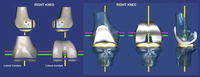
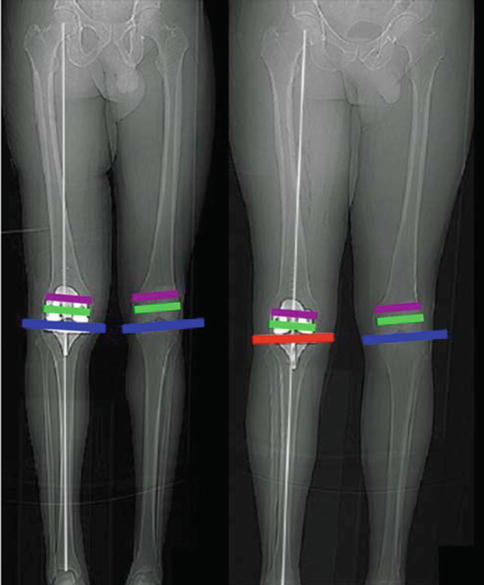
Fig. 13.1
The right femur (left) and kinematically aligned TKA (right) shows the relationships of the three kinematic axes of the knee with respect to the joint lines of the distal and posterior femoral resections and the 6-degree-of-freedom position of the components [16]. The flexion axis of the tibia is the green line, the flexion axis of the patella is the magenta line, and the longitudinal rotational axis of the tibia is the yellow line. All three axes are closely parallel or perpendicular to the joint lines. Compensating for wear and kerf and resecting bone from the distal and posterior femur condyles equal in thickness to the condyles of the femoral component kinematically align the femoral component
Fig. 13.2
Composite shows that the kinematically aligned TKA (left patient) restores the natural tibial-femoral joint surface (blue line) and limb (white line) and knee alignment and coaligns the axes of the femoral component with the flexion axes of the tibia (green line) and patella (magenta line) and that the mechanically aligned TKA (right patient) changes the natural tibial-femoral joint surface (red line) and limb and knee alignment and aligns the axes of the femoral component oblique to the flexion axes of the tibia and patella. Studies have shown that kinematic alignment establishes the same average limb and knee alignment as mechanical alignment and has less varus limb and knee outliers [5, 6, 23]
13.3.1 Kinematically Aligning the Femoral Component to the Natural Tibial-Femoral Articular Surface
Kinematically aligned TKA sets the femoral component at the natural angle and level of the distal (0°) and posterior (90°) joint line. This technique applies a distal and posterior femoral referencing guide at 0° and 90° of flexion, which are adjusted to compensate for wear and kerf and perform resections equal in thickness to the condyles of the femoral component (Figs. 13.3 and 13.4).
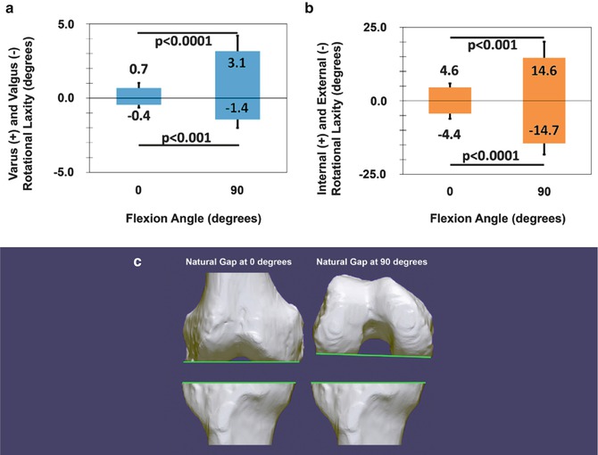
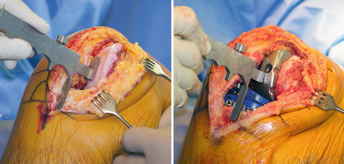
Fig. 13.3
A composite shows column graphs of the natural varus (+), valgus (−), internal (+), and external (−) rotational laxities of the normal knee at 0° and 90° of flexion (a, b) and the natural gaps of the knee at 0 and 90° of flexion after making the resections using kinematic alignment (c) [25]. Those paired columns connected by a p-value less than 0.05 indicate that the laxity at 90° is greater than at 0° of flexion. The flexion gap is asymmetrically shaped and greater laterally than medially at 90° of flexion and greater laterally and medially than at 0° of flexion. Error bars show ±1 standard deviation
Fig. 13.4
Intraoperative photographs of the right knee in 90° of flexion show the measurement of the natural anterior offset of the tibia from the worn distal medial articular surface of the femur in a knee with a varus deformity at the time of exposure (left) and at the time of reduction with the trial components (right). Compensating for 2 mm for cartilage wear on the distal medial femur and adjusting the anterior-posterior slope and the thickness of the tibial component until the internal and external rotation of the tibia approximates 14° and the normal anterior offset of the anterior tibia from the distal medial femoral condyle matches the knee at the time of exposure at 90° of flexion restore the natural anterior-posterior alignment and laxities of the knee
The surgical technique begins by assessing the locations of cartilage wear on the distal femur and removing worn cartilage to bone with a curette. The flexion-extension position of the femoral component is set by drilling a positioning rod 10 cm into the diaphysis of the femur, perpendicular to the distal joint, and parallel to the anterior femoral cortex (Fig. 13.5). The varus-valgus and proximal-distal positions of the femoral component are set by placing an assembly of the offset distal femoral referencing guide and distal femoral resection guide over the positioning rod in contact with the distal femur, which compensates for 2 mm of cartilage wear on the worn condyle(s) and sets the thicknesses of the distal medial and lateral femoral resections equal to the condylar thickness of the femoral component after compensating for cartilage wear and kerf [3, 15]. The anterior-posterior and internal-external rotation positions of the femoral component are set by placing a 0° rotation posterior referencing guide in contact with the posterior femoral condyles (Fig. 13.6).
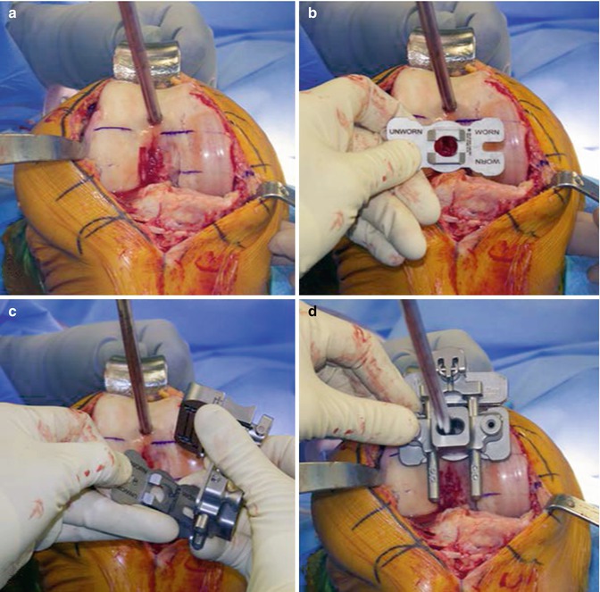
Fig. 13.5
 Aetiology of Patient Dissatisfaction Following Total Knee Arthroplasty
 Technological Aids in Total Knee Arthroplasty: Navigation, Patient-Specific Instrumentation, and Robotics
 Prosthetic Kinematics: Cruciate Retaining Versus Posterior Stabilized Versus Medial Pivot
 Longevity: Characteristics of a Well-Functioning, Long-Lasting Total Knee Arthroplasty
 Principles of Revision Total Knee Arthroplasty: Incisions, Approaches, Implant Removal and Debridement
 Periprosthetic Fractures


Composite of the right varus osteoarthritic knee shows the steps for kinematically aligning the femoral component at 0° of flexion. A positioning rod is inserted 10 cm into the diaphysis of the femur, perpendicular to the distal joint, and parallel to the anterior femoral cortex (a). An offset distal femoral referencing guide is selected that compensates for 2 mm of distal medial cartilage wear (b). The offset distal femoral referencing guide and distal femoral resection guide are assembled (c). The assembly is inserted over the positioning rod until in contact with the distal articular surface of the femur at 0° of flexion (d). These steps set the varus-valgus and flexion-extension rotation and proximal-distal translation of the femoral component to the natural articular surface of the femur
Related posts:
Aetiology of Patient Dissatisfaction Following Total Knee Arthroplasty
Technological Aids in Total Knee Arthroplasty: Navigation, Patient-Specific Instrumentation, and Robotics
Prosthetic Kinematics: Cruciate Retaining Versus Posterior Stabilized Versus Medial Pivot
Longevity: Characteristics of a Well-Functioning, Long-Lasting Total Knee Arthroplasty
Principles of Revision Total Knee Arthroplasty: Incisions, Approaches, Implant Removal and Debridement
Periprosthetic Fractures
Stay updated, free articles. Join our Telegram channel
Full access? Get Clinical Tree
