Fig. 16.1
(a) Diagram showing talar configuration which is wider anteriorly; (b) synovial recesses of the ankle and subtalar joints
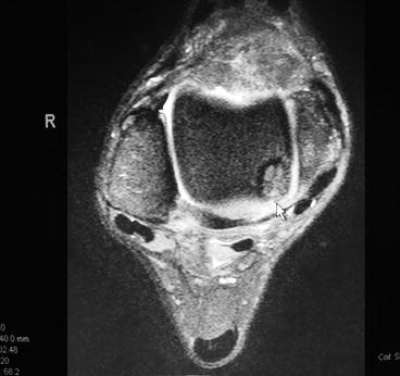
Fig. 16.2
MRI showing posteromedial lesion
Like with any surgical planning, the initial assessment and appropriate diagnosis of pathology is most important when deciding on the procedure to perform. Clinicians commonly will use MRI and high resolution CT imaging to help confirm or rule out defects to the talar dome and within the ankle joint.17–20 These imaging modalities are more sensitive than standard radiographs. If arthroscopy is the procedure of choice for a medial osteochondral lesion, then the following surgical technique using a Micro VectorTM (Smith Nephew, Andover, MA, USA) or Arthrex ankle (ArthrexTM, Naples, FL, USA) drill guide can be used to better access the joint (Fig. 16.3).
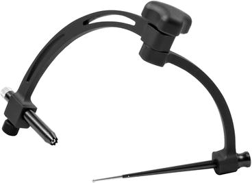
Fig. 16.3
ArthrexTM drill guide
16.1 Surgical Technique
First, the ankle is anesthetized. Using approximately 5 cc of lidocaine (plain or with epinephrine) anesthetize the traditional portal areas. Then insert an 18 gauge needle through one of the portals past the ankle joint capsule and inject approximately 5–6 cc of local anesthetic. This will provide both anesthesia and distention of the ankle joint. An additional 15 cc of normal saline is then injected for further distention of the joint. If general anesthesia is used, a thigh tourniquet can be utilized and inflated to 350–400 mmHg. When local anesthesia is used, a high ankle tourniquet can be applied and inflated to 250–300 mmHg.4 Some surgeons prefer not to place local anesthetic within the joint pre-operatively, but rather, anesthetize the joint proximally. This is due to the fact some prefer not to use a tourniquet in order to verify bleeding during marrow stimulation techniques, i.e., microfracture. An arthroscopic “Dual WaveTM” pump (Arthrex, Inc, Naples, FL USA) is preferred to maintain joint distraction (usually at 35 mmHg) and is an alternative to a tourniquet.
Using a noninvasive technique, distract the ankle joint.21,22 The first portal is anterior at the ankle level, lateral to the anterior lip of the medial malleolus, and medial to the tibialis anterior. It should be made midway between these two structures (Fig. 16.4). Make a 6-mm incision right at the anterior aspect of the joint and use a mosquito hemostat to bluntly dissect down to the capsule. The subcutaneous tissue is examined for neurovascular structures. Seeing none, the incision is deepened through the capsule and immediately fluid should be noted. Next insert the obturator and cannula (Fig. 16.5). At this time the obturator is removed, and the arthroscope is inserted through the cannula and connected to irrigation (ingress). Keeping the foot dorsiflexed while inserting instruments during anterior arthroscopy helps protect the articular surfaces. One should have a constant ingress and egress of fluid (often through another portal or attached to a shaver to allow for suction) to ensure the joint is distracted at all times while the arthroscope is in place; this will avoid damage to the cartilage surfaces, while allowing clearing of debris.4,5,23 Then we rotate the arthroscope laterally at the anterior aspect of the joint until visualization is made of the two branches of the superficial peroneal nerve, the intermediate dorsal cutaneous nerve, and the medial dorsal cutaneous nerve (Fig. 16.6). With the light shining from beneath (transillumination), a lateral incision is made between the two branches, which should be just lateral to the extensor digitorum longus tendon but medial to the anterior lip of the fibular malleolus right at the ankle level (Fig. 16.6). Next a 6-mm incision is made here and deepened using blunt dissection with a hemostat. The area is examined for any possibility of neurovascular structures which might be damaged when inserting the cannula. Next, an obturator and cannula are inserted until fluid return is noted after puncturing the synovial membrane. The arthroscope is then removed from the medial portal leaving cannula intact. The arthroscope is now inserted laterally, and examination of the joint can proceed (Fig. 16.7). At this stage, it is important to examine the area in front first which is the lateral shoulder and gutter (Fig. 16.8). Next, we focus our attention medially, going across the joint into the medial shoulder and then the medial gutter (Fig. 16.9). For better visualization, the arthroscope is now removed with the cannula left intact laterally and the arthroscope is now inserted into the medial cannula and examination of the medial gutter and then the posterior aspect of the joint can take place (Fig. 16.10). Once the arthroscope is in position and proper ingress and egress of fluid is established, use the full radius 3.5-mm shaver to clear away any hypertrophic synovium to get a better view of the talar defect. The lesion can then be treated via subchondral drilling, microfracture, curettage, or abrading the base.4,24
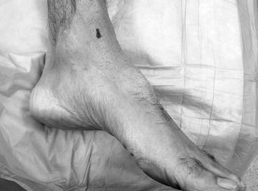
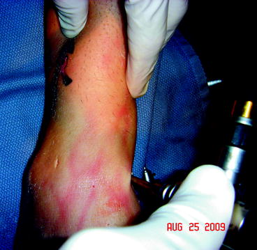
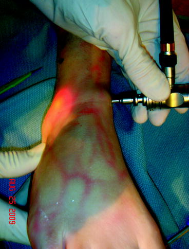
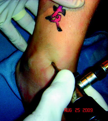
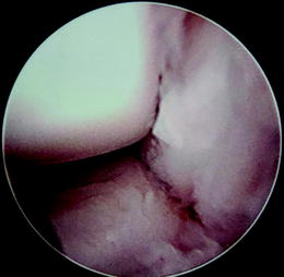
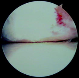
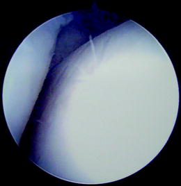
Fig. 16.4
Anteromedial portal
Fig. 16.5
Inserting obturator/cannula
Fig. 16.6
Transillumination to create anterolateral portal
Fig. 16.7
Insertion of arthroscope in anterolateral portal
Fig. 16.8
Arthroscopic view of lateral shoulder and gutter
Fig. 16.9
Arthroscopic lateral to medial view
Fig. 16.10
Medial gutter from medial portal
A technique to access difficult-to-visualize (and instrument) lesions was described by Grady and Hughes.25 If the defect is noted to be located within the posterior medial half of the talar dome and cannot be adequately accessed, a Micro Vector drill guide can be used to create an additional portal through the medial malleolus.25 (Fig. 16.11) The guide is made up of two curved articulating arms at 170° with constant alignment of the probe and guide regardless of the arm position. A 0.45, 0.62, or 0.125 k-wire guide is available with serrated tip to maintain bone position. The trephine used is 5.1 mm. Simply align the probe through existing medial portal and line up the adjustable end of the guide to the medial malleolus. The guide arms intersect (Fig. 16.12). Once the position is established, lock the hinge, and insert the 0.62 k-wire through the guide into the defect. Leaving the k-wire in place, remove the guide and bluntly dissect around the k-wire down to the medial malleolus. Next, a 5.1 mm trephine is placed over the k-wire and a core of bone is removed to access the ankle joint (Fig. 16.13). The defect should now be accessible for subchondral drilling using a 0.62 k-wire. This technique is designed to avoid potential “overheating” of bone which can occur during trans-malleolar and talar drilling (Fig. 16.14). Once completed, simply reinsert bony plug back into medial malleolus and repair periosteum using 3–0 vicryl. Next, release the joint distractor and suture the portal sites. The postoperative course should consist of a non-weight- bearing cast immobilization for 6–8 weeks if any windowing was performed. If the lesion was accessible via traditional portals, it is important to establish range-of-motion as soon as possible to prevent any adhesions from occurring and immediate weight-bearing is encouraged.23,26,27 More detail on treatment of talar defects is found in Chap. 8 in the Sports Medicine section of this text.
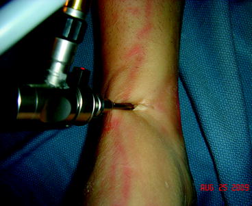
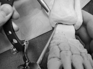
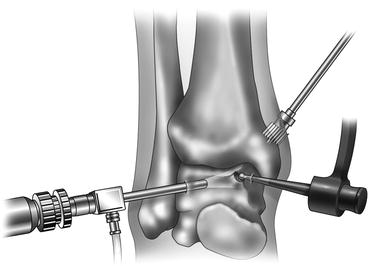
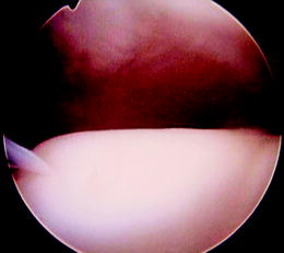
Fig. 16.11
View through anteromedial portal prior to creation of trephine hole through medial malleolus
Fig. 16.12
Micro VectorTM drill guide arms intersecting
Fig. 16.13
Trephine to remove bone plug
Fig. 16.14
Drilling lesion through medial malleolar hole
16.2 Discussion
Every surgical technique has complications and arthroscopy is no exception. The literature is scarce on this topic but several authors claim incidences as high as 17%, while others recording rates as low as approximately 1.8%.23,27,28 Those authors with less complications attribute this to experience and good anatomic dissection. In our personal experience, early range of motion can also help reduce complication rates. The complications reported include nerve injury, infection, direct injury to the articular cartilage, hemarthrosis, vascular injury, thermal injury, accelerated degenerative joint disease, and instrument malfunction.23,26,27,29,30 If an osteotomy is performed a nonunion becomes another postoperative concern. However, it has been the authors’ experience that patients, if chosen correctly, do very well post operatively. Additionally, in 2008 Ferkel et al. performed a long-term follow-up study on arthroscopic treatment of chronic OCD of the talus and had very good results from 2 to 12 years later.16 Depending on the severity of the pathology it will directly affect the patient’s results. When dealing with lesions that are not routinely seen or are more difficult to access through traditional portals, a Micro VectorTM drill guide can be considered to access posterior medial lesions.
16.3 Arthroscopic Ankle Arthrodesis
The first description of the ankle joint arthrodesis by Albert is dated back to 1879. Since then, an ankle fusion technique has been evolving from external to internal fixation including numerous implanted devices and cancellous screws. The latter increased the number of successful fusions and diminished the rate of complications such as infections and pseudoarthroses.31 More recently, advancement in arthroscopic technique has enabled surgeons to directly visualize the articular surface of joints which facilitated the debridement as well as subchondral bone resection techniques. The pioneer of the arthroscopic ankle arthrodesis was Schneider who was the first to describe the procedure in his video journal report in 1983.32Since then, the arthroscopic technique introduced many benefits over traditional open procedures.
16.3.1 Arthroscopic Ankle Arthrodesis Technique
Standard arthroscopic approaches as presented above are used. In addition, a posterolateral portal. An additional portal is created posterior-laterally. This is inserted through a guidance system whereby we put the obturator in through the anterior-lateral portal all the way through the posterior. When the point of the obturator is felt, we then make an incision right over the point. We then insert the cannula and obturator together through the posterior-lateral portal. This gives good visualization. This portal can be “free-handed” by making an incision just lateral to the Achilles tendon (thereby avoiding the sural nerve) and at the level 1 cm above the fibular tip. The posterior-medial portal is seldom used. The patient can be put in the prone position. Both posterolateral and posteromedial portals can be used in this position. This is discussed in Chap. 17.
Using the anterior-medial portal and a surgical abrader, the cartilage is denuded down to bleeding bone as shown in Fig. 16.15. It should be noted that we can only get to the middle of the talus through this portal. We then go ahead all the way across the medial side and the anterior-medial aspect. That is with the working channel medial and the scope laterally. We then switch the abrader laterally in the scope medially, and abrade the lateral-anterior aspect of the joint. Through the posterior incision described above, we then insert a working channel only. While visualizing from anteriorly, we are able to abrade the entire posterior cartilage down to bleeding bone. It should be noted that we can get up to 6.5 mm of distraction with the described technique of non-invasive distraction. This should be adequate to get the scope to at least seek when you reach the peak on the talus with the abrader. The patient may need to be positioned prone to remove all the posterior ankle cartilage if distraction and the posterolateral portal does not allow access. After the articular cartilage is removed, the subchondral surfaces are noted to be bleeding (suction is used to evacuate this), we then insert guide wires as shown, one medial and one lateral to the tibia, intersecting in the middle as show (Fig. 16.16). We then insert cannulated screws through percutaneous incisions on the medial and lateral aspect of the tibia. After noting the placement is correct arthroscopically, we remove the arthroscope, compress the ankle, remove the distraction, compress the ankle (if an external fixator is used), and then we insert the screws in progressive fashion (Fig. 16.17). If one cannot achieve appropriate position with adequate dorsiflexion, it may be necessary to take more off anteriorly than posteriorly from the talo-tibial joint. Soft tissue posterior lengthening may need to be performed. This can be performed endoscopically of the Gastrocnemius in the supine position. Joint resection can be done either with an abrader or with an oval burr. After irrigation is performed at the end of the procedure, the incisions are then closed using one simple interrupted suture of 4–0 ProleneTM. The wound is covered with AdapticTM or XeroformTM, and 4×4 gauze sponges and a posterior splint is applied. Post-operatively, the patient is kept non-weight-bearing for 6 weeks followed by weight-bearing casting for the next month, after which time, if radiographic union has occurred, the patient may begin ambulating with an ankle brace.
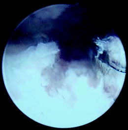
Fig. 16.15
Burring of degenerated cartilage
Fig. 16.16
Intra-operative guidewires for screw placement for arthroscopic ankle arthrodesis (Photos (a) – courtesy of Michael Lee, DPM; (b, c) – courtesy of Jack Schuberth, DPM)
Fig. 16.17
(a, b) Screw placement after arthroscopic ankle arthrodesis (Photo Courtesy of Michael Lee, DPM)
16.3.2 Discussion
Ogilvie-Harris and colleagues were one of the first investigators who performed in depth analysis of the arthroscopic ankle fusion. The study “Arthroscopically Assisted Arthrodesis for Osteoarthritic Ankle” published in 1993 reinforced the previous findings of Myerson and Quill in “Ankle Arthrodesis – a Comparison of an Arthroscopic and an Open Method of Treatment” published in 1991 and proved that procedure was, indeed, beneficial.32,33 In addition, Ogilvie-Harris with coauthors established the average time of radiographic union and assessed functional results 2 years after the procedure. The authors carefully selected 19 patients with ankle arthritis who did not show evidence of frontal plane ankle deformities, rheumatoid arthritis, vascular or neural abnormalities in order to eliminate possible failures due to patients’ comorbidities. Although the procedure protocol in many ways was similar to the modern techniques, no distraction device was used and the ankle alignment was achieved at 90° with respect to the tibial bisection without any frontal plane angulations. The results of the study showed striking decrease in postoperative pain and duration of hospitalization. Ten of 19 patients showed signs of radiographic union by the second postoperative month, 5 by the end of the third, 1 by the fifth and last by the sixth. Two patients developed a nonunion one of which was resolved with an open ankle arthrodesis. Among these patients, 2 had fair results, 4 had good results, and 12 had excellent results.32
Related posts:


Stay updated, free articles. Join our Telegram channel

Full access? Get Clinical Tree


