Fig. 17.1
The user seated at the master console of the Taurus robot-assisted surgery system. The Leap Motion sensor placed below can track two hands to control the position and orientation of each end effector. Inset shows a custom fixture for a scalpel mounted on the Taurus end-effector in one arm and in the other surgical tweezers
The comparative study includes gathering information from optical sensors (Kinect [7] and Leap Motion [16]) and pedals as the touch-less interfaces, and compare those to the performance delivered through touch-based interfaces such as keyboards, 3D joysticks (e.g. Hydra [17]) and haptic controllers (e.g. Omega 7 [18]). The measured metrics include deviation error when following a reference annotation, control variance, task completion time and number of errors within each trial.
The outline for the remaining sections of this work is as follows. In section “Related Work”, an overview of related work and the state of the art is provided. The next section offers a general view of the system with a brief description regarding the processing modules. Following that is a description of the kinematic configuration space and the trajectory generation of the Taurus robot, along with the different mappings from the interfaces to the robot and other details regarding each interface. The experiments are described subsequently with their corresponding results in section “Experiments: Settings and Results”. To finish, the conclusions followed by recommendations and future work.
Related Work
With the aim of improving performance and success rates for MIS, the field has been incorporating new sensors and control based technologies, making way for a new field in robotic minimally invasive surgery (RMIS). The most recognized example is the da Vinci robot [1], which rely on having the surgeon operate using encumbered interfaces to guide the robot through the surgical procedure. This form of control is also found in other state-of-the-art robots since it often provides tactile sensory information through haptics to restore “the real feeling of touch” to the operating surgeon. However, at the same time, this modality of control leads to limited range of manual operation [19], sense of detachment [20] and arises problems with surgical asepsis [21]. Some of these limitations could be tackled using touchless interfaces as a potential solution. The current gap is the lack of tactile information, existing in those touch-based interfaces previously discussed.
Sensorial substitution methods offer an attractive alternative to direct force feedback. Using these methods, feedback is delivered through other alternative modalities which are available to the user [22]. One example is using the visual system in a surgical teleoperation setting to provide information about skin contact, depth of incision or tissue manipulation [13]. Another option is to provide airborne force-feedback using air bursts aimed at the user’s hands [10]. A different approach to convey force is through ultrasound generated waves directly onto the users’ bare hands [23]. These touchless feedback methods allow the use of new interfaces based on natural free gestures, widely used in other human-robot interaction applications currently [24]. The main benefits of commodity sensors like Kinect, Leap Motion or the MYO arm band, are lower costs than many haptic devices and their increasing popularity in gaming consoles. Such sensors are pervasive and widely used for real-time hand gesture recognition [25, 26].
Previous research has been exploring the use of touchless hand gestures as a form for interacting with robots in the OR. For example, Jacob et al. [21] developed a robotic scrub nurse which delivers surgical instruments based on real-time hand gesture recognition [21]. Kim et al. [27] used the da Vinci robot to compare task performance between touch-based control interfaces and Kinect. In the latter, high latency and errors were found in the Kinect based control, leading to underperformance compared to the alternatives. Additional work has been done in this direction without tangible results [28, 29]. Some other work has been focused on controlling devices other than robots in the OR. Hartmann and Schlaefer [30] used the Kinect sensor for automating the OR lighting [30]. In Wachs et al. [24] hand gestures were adopted for browsing radiological images [30, 31]. Mouth gestures were also tested as a way to control the da Vinci Robot [32].
None of the works described include a systematic evaluation of touch-based and touch-less interfaces for robotic surgery performance assessment. The current chapter describes: (a) the development of a touchless hand gesture based interface for controlling a surgical robot and validated through a mock procedure, and (b) a comparison between touch-based and touchless interfaces in a clinically relevant context with corresponding performance metrics. Technical and theoretical findings are also reported related to the relationship between the user interaction space and the task space, and their effect in task performance.
System Architecture
The system architecture is presented in Fig. 17.2. Using one of the five interfaces available, the user performs gestures to control the Taurus’ navigation to complete a given task. These gestures are part of the lexicon which maps specific instructions to gestures through image processing, segmentation and registration processes. Once the gesture is recognized, a motion trajectory is generated to replicate the user’s motion in the robot space through a 3D projection and coordinate mapping of the user space. Subsequently, the trajectory is converted to robotic commands using the Robot Control Scheme module shown below.
Fig. 17.2
System architecture
While performing the task, the user is able to receive feedback from Taurus by both visual and sound cues. Using the stereo cameras mounted on the robot, a 3D image is generated and presented to the user, as well as information regarding stiffness, position and orientation of the tooltips. This information is presented to the user through color and sound feedback modalities. Based on this feedback, the user generates the subsequent set of commands to complete the task.
Taurus is a high fidelity telemanipulation robot with a 3D HD display developed by SRI (Menlo Park, CA). Taurus has two dexterous and compact arms which can be applied to the surgical setting; it enables surgical-like precision in a modular, portable frame. As shown in Figs. 17.3 and 17.4, it has two independently controlled manipulators with seven degrees of freedom each. One end-effector includes a custom fixture for mounting a scalpel, while the other functions as surgical tweezers.
Fig. 17.3
Picture of Taurus with a scalpel mounted on the left gripper
Fig. 17.4
The Taurus’ manipulator degrees of freedom
Real-time visual feedback information is provided using a stereoscopic camera system and presented to the user in a 3D stereo display. The left and right views are accurately integrated using Nvidia’s stereoscopic glasses 3D Vision 2.
Kinematic Configuration Space and Trajectory Generation
In order to control both the position and the orientation of each of Taurus’ end-effector, packets are transmitted to the robot server at a rate of 250 packets per second. The kinematic configuration is determined by a homogeneous transform 4-by-4 matrix X (one for each arm), shown in Eq. (17.1), which contains a 3-by-3 sub-matrix on the upper left representing the rotation transform (from user to task space); on the upper right holds the 3-by-1 position vector with the coordinates for the end effector; and finally the last row is formed by a zero 1-by-3 matrix and a scaling factor.
![$$ X=\left[\begin{array}{cccc}{X}_{11}& {X}_{12}& {X}_{13}& x\\ {}{X}_{21}& {X}_{22}& {X}_{23}& y\\ {}{X}_{31}& {X}_{32}& {X}_{33}& z\\ {}0& 0& 0& 1\end{array}\right] $$](/wp-content/uploads/2016/09/A321277_1_En_17_Chapter_Equ1.gif)
(17.1)
Each vector of the rotation matrix relates one axis of user coordinates to robot coordinates. The equations in Eq. (17.2) were used to compute the roll (α), pitch (β) and yaw (γ) angles and later on re-coded to real-world-coordinates by multiplying rotational operators, as shown in Eq. (17.3), using ROT as a rotation function along a specified axis and angle [33].
![$$ \begin{array}{l} Rot\left(g,\;b,\;a\right)= ROT\left(\widehat{Z},\;a\right) ROT\left(\widehat{\mathrm{Y}},\;b\right) ROT\left(\widehat{X},\;g\right)\\ {}=\left[\begin{array}{ccc}ca& -sa& 0\\ {}sa& ca& 0\\ {}0& 0& 1\end{array}\right]\left[\begin{array}{ccc}cb& 0& -sb\\ {}0& 1& 0\\ {}sb& 0& cb\end{array}\right]\left[\begin{array}{ccc}1& 0& 0\\ {}0& cg& -sg\\ {}0& sg& cg\end{array}\right]\end{array} $$](/wp-content/uploads/2016/09/A321277_1_En_17_Chapter_Equ3.gif)
(17.2)
(17.3)
Where cα and sα are shorthand for (cos α) and (sin α) respectively. Due to mechanical constraints, Taurus cannot respond accurately to large rotation increments. Therefore, to assure safe operation, the maximum rotation increment was limited to 0.1°. Therefore, the following algorithm was implemented to perform a piecewise-linear approximation of the overall rotation angle.
Algorithm 17.1: Trajectory Generation
1: Input: Transform matrix X, step_length τ
3: τ = Get_current_frame_from_robot
5:  // number of iterations
// number of iterations 6:  // rotation step
// rotation step 7: For i = 1 : N
8: P = Construct_control_packet(Δα, Δβ, Δγ, τ)
9: Send_to_Taurus(P)
10: End
Mapping Interfaces to Actions
Five interfaces were selected for the comparative study, among which there are three touch-based and two touchless. The touch-based interfaces included: a regular keyboard, a Hydra gaming controller [17] and Omega 7 haptics device [18]. A Leap Motion controller [16] and a Kinect [7] were used as the touchless interfaces. A picture of all interfaces is shown in Fig. 17.5.
Fig. 17.5
Five different interfaces to control Taurus: touch-based and touch-less among them
A foot pedal was implemented along with all five interfaces to toggle the engage/disengage servo mechanism, which helped the operators switch the working space or stay idle. Also, the raw data gathered from the sensors was filtered using a low-pass filter to cancel the noise variation caused by the control input modalities. The following subsections give further details about the key modules included.
Registration
The registration process is a prerequisite of interface operation to retrieve parameters once the interface is selected. It consists on mapping the reference frame in which the user works with the frame associated with the task space. In the beginning of teleoperation, the first 10 control input coordinates are recorded and an origin of the user space is generated from the running average of them. This origin of the user space is then mapped to the origin of the robot space. During teleoperation, the operator’s movement relative to this origin is then interpreted as practical control instructions. This process applies to all the interfaces other than the keyboard, since the latter does not use 3D coordinates to evoke control motions, and rather keystrokes are used instead. The registration process takes place whenever the foot pedal is reactivated by the user, since each time the user starts the teleoperation from different positions and thus the origin of the user space should be updated every time before the practical teleoperation.
Safety Operation and Region Determination
Virtual bounding boxes are implemented around both the user and task space in order to ensure safe motion during robot teleoperating. In the user space, a virtual rectangular region is created around the user hands to maintain the input coordinates within a permissible operational range. Working within this region also assures that the hands are within the optical sensors’ field of view. Analogously, a similar region is established around the robot at the task space. This region limits the outer reach of the robot and assures that the robot’s movements are maintained within the operational range. The robot’s working space is cut in half, as shown in Fig. 17.6, allowing each arm to move only in its half with some overlapping in the middle. This assures that the robot forearms do not collide with the camera. When the limits of the bounding box are reached, a sound beep goes off to alert the user about this situation.
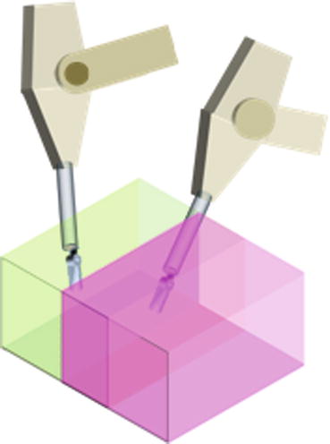
Fig. 17.6
Taurus’ operation space. The left gripper is allowed to work only in the pink region and right gripper in the green region. Both grippers can reach the overlapping area in the middle
Visual and Auditory Feedback
As mentioned in previous sections, the biggest drawback of working with hand gestures using touchless interfaces for RAS is the lack of force feedback. This problem is addressed using sensory substitution techniques based on vision and audio cues. The operator receives physical contact information about the force exhorted at the tooltip through two bar graphs; each bar indicates the force of one tooltip, as shown in Fig. 17.7. The size and color of each bar changes proportionally with the amount of force applied to the end effector. At the same time, a beep sound is generated with its pitch modulated according to the force’s magnitude. Both acoustic and visual channels are meant to increase the user’s awareness while performing the surgical task. Algorithm 17.2 describes the procedure of generating force based on report tooltip position and the operator’s hand position. Due to limited network communication bandwidth, a delay is generated between the time a target position is sent to the robot and the actual robot response is received, creating a constant lag between the user’s hand position and the reported robot’s position. The constant dragging force generated by this effect is compensated by factoring the robot’s arm speed by a damping factor, when calculating the force feedback. Since the damping factor was selected empirically, this haptic compensation could generate false alarms when fast hand movement occurs. Therefore, a threshold was selected to consider a warning signal as valid.
 Virtual Preoperative Planning
 Computational Image-Guided Technologies in Cranio-Maxillofacial Soft Tissue Planning and Simulation
 Patient-Specific Instruments in Orthopedics
 Virtual Cranio-Maxillofacial Surgery Planning with Stereo Graphics and Haptics
 Computer Simulation Surgery for Deformity Correction of the Upper Extremity
 Navigation in Spinal Surgery


Related posts:
Virtual Preoperative Planning
Computational Image-Guided Technologies in Cranio-Maxillofacial Soft Tissue Planning and Simulation
Patient-Specific Instruments in Orthopedics
Virtual Cranio-Maxillofacial Surgery Planning with Stereo Graphics and Haptics
Computer Simulation Surgery for Deformity Correction of the Upper Extremity
Navigation in Spinal Surgery
Stay updated, free articles. Join our Telegram channel
Full access? Get Clinical Tree
