KINESIOLOGY BASICS
Successful diagnosis and treatment of musculoskeletal dysfunction requires an understanding of both basic anatomy and the dynamic relationship of anatomic structures to one another known as functional anatomy. Biomechanics is the study of the physical actions of forces or mechanics applied to a biologic system and the implications this has on anatomic and functional relationships. The forces can be divided into static and dynamic types. Static biomechanics involve a physiologic system in which the forces result in a state of equilibrium with a net of zero change in the system velocity. In this case the body can remain at rest or in motion; however, a constant velocity persists due to the balance of forces. Dynamic forces result in net acceleration of the physiologic system due to the unbalanced application of forces.
Kinetics is the study of motion; this is a general term with implications across many sciences. Human kinetics is the study of motion of the human body with a focus on the forces that produce motion. The structure and stability of each extremity reflect the forces imparted and, ultimately, the functional demands placed on the limb. The functional demands of the upper limb are vastly different than those of the lower limb, and the forces imparted are therefore different. The amount of movement versus amount of stability necessary for function at a joint governs its size, shape, and infrastructure. This difference is clearly seen when the hip joint is compared with the glenohumeral joint. Kinematics is a branch of science that describes the motion of points, objects, or systems without consideration of the cause of this motion, and can also be described as the geometry of motion. This includes consideration of time, displacement, velocity, acceleration, and space factors of a system’s motion.
Two types of motion occur about most joints to varying degrees based on function: translation (linear displacement) and rotation (angular displacement). These two movements occur within the three orthogonal planes: the coronal, sagittal, and transverse. Although complex motion occurs across many planes simultaneously, the motion can be subdivided into the aforementioned planes with the use of image capture and computer-aided motion analysis. When analyzing motion that is occurring in any one plane, the structure that serves as or creates that axis of rotation, perpendicular to the major plane of motion, must be determined. For example, motion in the coronal plane occurs about an axis of rotation that is in the sagittal plane. If one understands the structures that determine the axis of rotation, these can then be examined for pathologic disease processes or function.
Kinesiology requires an understanding of functional anatomy and combines the sciences of kinetics and kinematics as well as biomechanics, anatomy, and physiology in the study of movement. It is through a fundamental understanding of kinesiology and implementation of its principles that one can recognize normal and abnormal function and use this information to optimize patient recovery, performance, and avoidance of injury.
Having a framework within which to interpret abnormal function is vital to the success of a rehabilitation physician. One such system has been proposed by Dr. Gerald Herbison of Thomas Jefferson University Hospital in Philadelphia. Aberrant motion is examined and then classified as being due to pain, paralysis or paresis, or contracture. Pain alone, through increased afferent input, can inhibit muscle contraction. Without muscle contraction, there is decreased joint stability and joint motion. Paralysis or weakness clearly can affect joint motion through the lack of either concentric or eccentric muscle contraction, but also due to improper joint positioning for optimal motion, and possible joint instability due to the lack of necessary agonist–antagonist muscle function across a joint. Finally, joint contracture, physically impeded motion, can occur with either normal or abnormal soft tissue physiologic findings. If these factors are considered in the analysis of motion, the cause of the abnormality, and ultimately a diagnosis, can be determined within a clinical context.
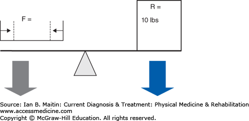
Within the human body, the musculoskeletal system uses three main types of mechanics to produce motion: levers, wheel-axles, and pulleys. A lever uses a rigid bar that turns about an axis of rotation, or fulcrum. In the human body bones function as the levers, joints compose the axes of rotation, and muscles produce force that cause motion. All lever systems contain these three components; however, the arrangement of these components may differ across different types of joints involved in different types of movements (Figure 4–1). The force or effort is due to contraction of a muscle and is usually represented by the insertion of the muscle on a bone. The resistance can be the center of gravity of the lever or the location of the application of some external resistance. In a type 1 lever arm (Figure 4–2A), the fulcrum is located between the resistance and the force; an example of this is elbow extension with the arm in an overhead position. The triceps inserts on the olecranon, the elbow joint is distal to this point, and the resistance force is the center of gravity of the forearm. In type 2 lever arms (Figure 4–2B), the resistance is located between the fulcrum and the force. There are few physiologic examples of this type of lever arm, but a common example is a heel raise. In a heel raise the axis of rotation is located distally at the metatarsophalangeal joint, the resistance is the weight of the body between the axis and the applied force of contraction of the gastrocnemius–soleus complex proximally at the calcaneus. Finally, in a type 3 lever arm (Figure 4–2C), the force is located between the fulcrum and the resistance. This is the most common type of lever arm. Examples of a type 3 lever arm are the brachialis muscle and the iliopsoas muscles. Here the axis of rotation is proximal, the resistance force at the center of mass of the limb is distal, and the contracting muscle force is at some point between the two.
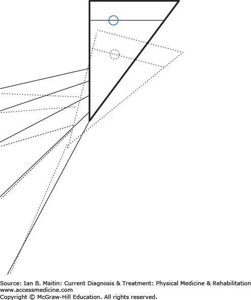
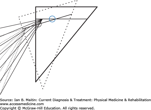
Figure 4–2
Lever arms. A. Type 1 lever arm. B. Type 2 lever arm. The resistance is the center of mass, and this falls between the force of the contraction of the muscles acting in plantar flexion and the fulcrum, which is the metatarsal-phalangeal joint. C. Type 3 lever arm. The resistance is the weight of the forearm and any weight carried in the hand. The applied force is due to contraction of the elbow flexor complex where the insertion of these muscles on the proximal portion of the radius and ulna are distal to the axis of rotation of the elbow joint. This is the most common physiologic lever arm.
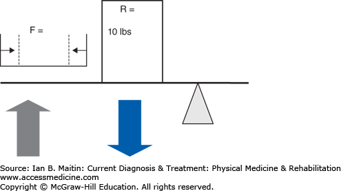
The mechanical advantage (Figure 4–3) of a system can be calculated by first calculating the workload of the system and then calculating the differential between the workload of the internal moment arm (muscle force) and the external moment arm (load), where the length of the force arm (df) is divided by the length of the resistance arm (dr) over which a force is applied. The workload can then be calculated as (F × df) / (R × dr), where F and R are the magnitude of the force of the applied force and the resistance, respectively. A mechanical advantage ratio greater than 1 favors the internal moment arm. In a type 2 system (Figure 4–4), panels A and B), the internal moment arm is always larger than the external moment arm, thereby creating a condition in which less force may be needed to overcome a very large external force. This is why it is difficult to test the gastrocnemius–soleus system with the patient either sitting or lying prone. The external force applied by the examiner will be far less than that produced during weight bearing; therefore, even if weakness is present, it is unlikely to be noted due to the mechanical advantage maintained by the plantar flexors as a type 2 lever arm. Type 2 lever arms always have a mechanical advantage ratio greater than 1, making these systems very efficient (see Clinical Correlation 4–1). In a type 3 system (Figure 4–3, panels C and D), the most common type physiologically, the internal lever arm is always shorter than the external lever arm, and a greater internal force is always necessary to overcome the external force. This type of system produces relatively little mechanical advantage, with the ratio being less than 1.
CLINICAL CORRELATION 4–1 Weakness of the Ankle Plantar Flexors
The ankle plantar flexors exemplify a type 2 lever system. As such, the muscle and the muscle lever arm always maintain a mechanical advantage over the external force and load lever arm. This is why it is difficult to determine the presence of weakness in the ankle plantar flexors when the examiner grasps the foot with his or her hands and applies an opposite force. The most accurate means of assessing weakness in this muscle group is to engage the muscle in a more physiologic activity, such as heel raises, where a much larger force than the weight of the person can be added.
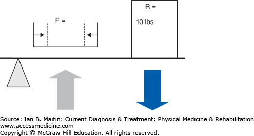
Figure 4–3
Mechanical advantage. Relationship of length of moment arm (distance A–D) and muscle contraction (represented by size of green arrow). There is increasing distance from insertion point A through D, which results in an increase in the length of the lever arm of the contracting muscle. The force of muscle contraction produces angular displacement of the distal limb; this force is called torque. The force of torque is T = F × d, where F is the magnitude of muscle contraction (in Newtons) and d is the length of the lever arm. There is an inverse relationship between muscle contraction (F) and lever arm length (d), whereby to produce the same amount of angular displacement or torque, with increased distance, less muscle contraction force is required to balance the externally applied resistance. With muscle contraction force held constant, mechanical advantage refers to the amount of work required to move an external resistance. Following the same principle, with increased lever arm or, in this case, moment arm, less work is required to displace the same external load that is proportional to the length of the moment arm. Therefore, systems with longer lever arms (insertion point D) will have a mechanical advantage (yellow-shaded area) over those with shorter lever arms (point A), if the magnitude of force of muscle contraction (green arrows) is proportionally smaller compared to the length of the moment arm. For instance, at insertion point A, the force of muscle contraction must be equal to the 10 lb of external load, whereas at point D, the force of muscle contraction is one quarter the force at A, due to the increased length of the moment arm. The mechanical advantage occurs due to the decreased stress and work incurred by the contracting muscle with longer moment arms.
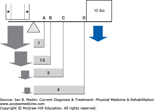
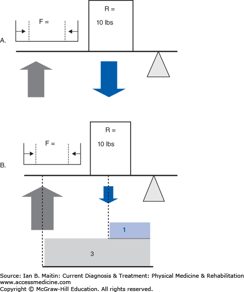
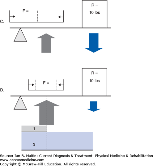
Figure 4–4
Comparison of the mechanical advantage of different types of lever arms (A–D). A. The relationship of the vector of the force produced by muscle contraction versus resistance of externally applied force and the fulcrum for rotation or angular displacement in a type 2 lever arm. B. The mechanical advantage (shaded area) of this system, a type 2 lever arm system, due to the larger moment arm (distance of arrow from fulcrum) of the contracting muscle’s long lever arm compared to the lever arm of the external force. This type of system has a mechanical advantage ratio > 1. This is produced by the moment arm of the muscle force (F × df)/(R × dr). Thus, with a force equal to resistance, there is a mechanical advantage > 1 due to the longer moment arm from the muscle contraction based on the orientation of its insertion. During a single-leg stance, in which the external load that must be overcome by the active muscles is usually approximately 1.5–2 times body weight, this muscle group is capable of producing forces of contraction likely greater than 200–400 kg. Clearly, an externally applied force magnitudes smaller, produced by the force of one upper limb during muscle testing, will not be able to overcome this muscle unless significant weakness is present. C. The relationship of the vector of the force produced by muscle contraction versus resistance of externally applied force and the fulcrum for rotation or angular displacement in a type 3 lever arm. D. The mechanical advantage of this system, a type 3 lever arm system, is due to the larger moment arm of the external resistance’s long lever arm compared to the lever arm of the muscle force. There is a mechanical advantage ratio < 1, as demonstrated by (F × df)/(R × dr). To overcome the mechanical advantage of the external force in this type of system, the magnitude increase of muscle force of contraction must be proportional to the length advantage of the external load. This is shown by the proportionally larger muscle force arrow (demonstrated by the grey force arrow).
The wheel-and-axle relationship has many physiologic correlates and has implications for angular acceleration or torque, and magnitude of movement. In most systems, the wheel radius is larger than the axle radius. This relationship holds for the force arm; therefore, the wheel will have a mechanical advantage over the axle. For this reason, a smaller force may be applied to the wheel to move a relatively larger resistance applied to the axle. If the force is reversed and so applied to the axle, the wheel will spin faster than the axis and travel a greater distance because of the same mechanical advantage relationship.
An example of such a system is the humerus and forearm. The humerus serves as an axis of rotation. The humeral external rotators contract a small amount but produce up to 90 degrees of external rotation. The distance that the forearm and hand will travel is far greater than the length of muscle shortening between the muscle origin and insertion at the axis of rotation (axle). Similarly, with internal rotation, as in the acceleration phase of pitching, joint displacement of the glenohumeral joint would likely be deleterious in light of the ultimate speed with which the ball leaves a pitcher’s hand. However, as described, due to the distance relationship, the speed of the humeral internal rotation is reduced by a magnitude proportional to the length of the wheel radius.
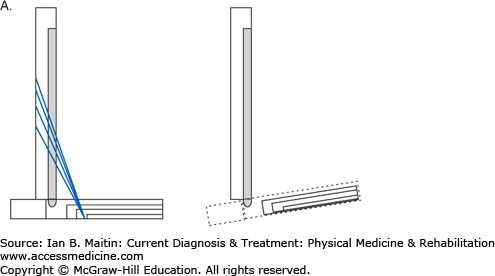
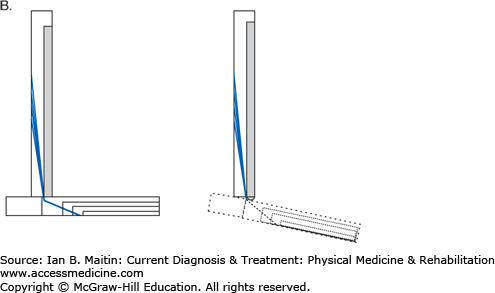
Although less numerous than the other mechanical systems, pulley systems exist in the human body and serve to change the effective direction of an applied force. This decreases work and makes movement of an object easier. Pulleys can be singular or combined in a system in which the mechanical advantage of one pulley is equal to 1, and the addition of each new pulley increases the mechanical advantage by a factor of 1. A physiologic example of a pulley system is seen in the peroneus longus and brevis muscles, which arise from the proximal and middle third of the fibula and insert on the base of the first and fifth metatarsals, respectively. Over their course, they run posterior to the distal fibula. Without traversing this course, the insertion of the peroneus longus muscle would be on the base of the first metatarsal and the muscle would then function more completely as an ankle dorsiflexor. The distal fibula functions to create a pulley system, in which a change in the force vector is created by the peroneus muscle complex. In this case the forces applied to the respective metatarsal heads now serve to plantar flex and evert the foot (Figure 4–5).
Figure 4–5
Force vectors of the peroneus muscle complex. A. The peroneus complex force vector would result in dorsiflexion and eversion, absent the pulley effect created by the lateral malleolus. B. The peroneus complex force vector produces plantar flexion and eversion due to the pulley created by its course posterior to the lateral malleolus.
OPEN CHAIN & CLOSED CHAIN KINEMATICS: AN INTERACTION OF MUSCLE & JOINT
Muscle action describes motion in an open chain system or a closed chain system. In an open chain system, the distal link is free to move while the more proximal links are fixed. In a closed chain system the distal link is fixed and the proximal end is free to move. Steidler translated this system to human motion in the 1940s, proposing that each link in the chain is a limb and the interaction of two links is similar to a joint. Most physiologic motion involves a closed chain system, because the forces applied to the distal limb are usually weight bearing. Weight bearing imparts an axial load through a joint which, in combination with the ground reactive force, creates a fixed limb. In contrast, in an open chain system, the joint forces at the distal segment are usually perpendicular, producing angular acceleration at the joint and not compression. Once the distal limb is engaged in a closed system, the motion at any one joint in the limb will affect all other joints in the system; this is in direct opposition to open chain kinematics, where all joint motion is independent of motion at the other joints in the limb. Most muscles, especially during the gait cycle, function in a closed chain system and in a manner that may be counterintuitive to their normal open chain activity. For example, the gluteus maximus normally functions as an external rotator and an extensor of the hip; however, from initial contact through the loading phase of gait it is eccentrically active and functions as a knee extensor. During this period, the function of the muscle is to counteract the ground reaction force, which falls behind the knee and produces a knee flexion moment (Figure 4–6). If there is fatigue or weakness of the quadriceps, this may lead to knee buckling; however, the function of this muscle can help to reduce this effect.
Figure 4–6
Related posts:


Stay updated, free articles. Join our Telegram channel

Full access? Get Clinical Tree


