PROCEDURE 35 Operative Management of Ankle Fractures


Examination/Imaging
PHYSICAL EXAMINATION
 Complete regional examination of the lower extremity to rule out concomitant injury.
• Local associated injuries involving the talus, calcaneus, base of the fifth metatarsal, and Lisfranc joint must be sought.


IMAGING STUDIES

 Anteroposterior, mortise, and lateral views are obtained. Knowledge of the anatomy allows one to fully understand the information obtained from the radiographs.
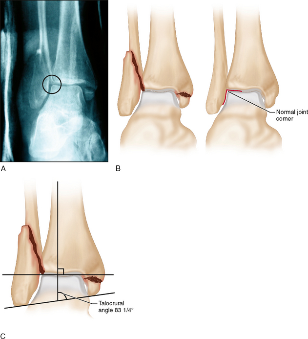
• Lateral malleolar shortening is seen as disruption of subchondral bone continuity along the fibula relative to the lateral tibia at the joint level. A smooth arc should join the two subchondral surfaces, but in the displaced bimalleolar fracture seen in Figure 1, the subchondral bone does not match the normal contour of the talus (Fig. 1A and 1B). The result is an increase above normal in the talocrural angle (Fig. 1C); a small amount of malleolar shortening is present also.
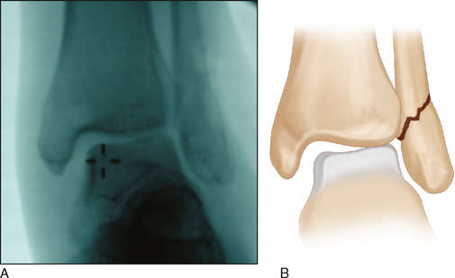
• Lateral talar shift is noted in radiographs in which the medial clear space is greater than the superior joint space. Figure 2A is an intraoperative stress view of a Weber type B fracture showing widening of the medial clear space between the talus and the medial malleolus (Fig. 2B), versus that between the talus and the distal tibia.
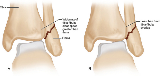
• Diagnosis of syndesmosis disruption is based on AP and mortise view measurements taken at 1 cm above the ankle joint. On the AP view, there is less than 1 mm of tibia-fibula overlap and widening of the tibia-fibula clear space of greater than 4 mm (Fig. 3A). On the mortise view, there is less than 1 mm of tibia-fibula overlap (Fig. 3B).
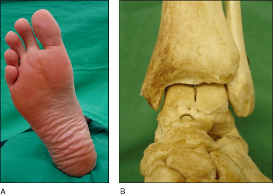
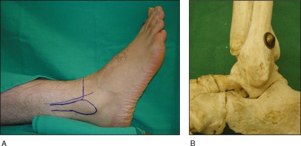
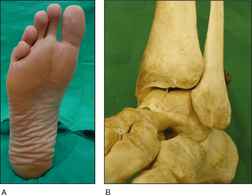
 Patient positioning is important to obtain the correct view.
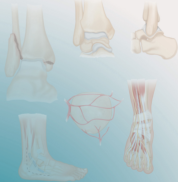
• Figures 4–6 show the orientation of the foot and the skeleton when correctly positioned for radiographs in the AP (Fig. 4A and 4B), lateral (Fig. 5A and 5B), and mortise (Fig. 6A and 6B) views.
• The skeletal models seen in Figures 4–6 show the posterolateral position and areas of subchondral condensation of the fibula shown in Figure 1A.

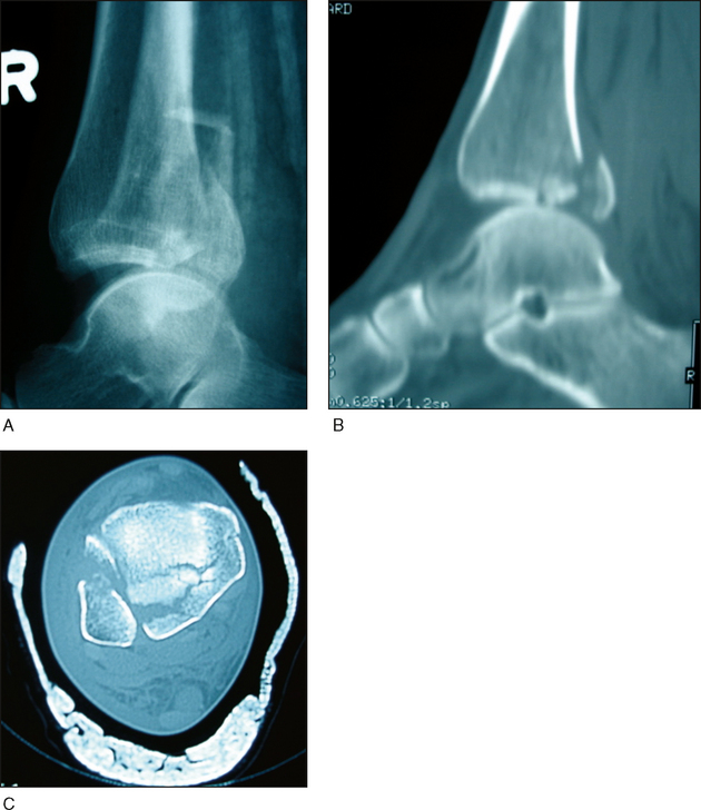
 Computed tomography (CT) scanning may define marginal impaction and talar osteochondral fragments, as for the trimalleolar ankle fracture-dislocations shown in Figure 7A.
Surgical Anatomy

 Structures of note in the medial ankle (Fig. 9A) include the following:
• Anterior and posterior colliculi of the medial malleolus (Fig. 9B), and the groove for the tibialis posterior tendon.


Positioning


Portals/Exposures
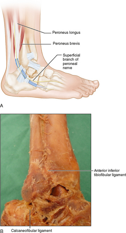
 Lateral (Fig. 11)
• A direct lateral incision over the fibula allows for access to all sides of the fibula (anterior, posterior, and lateral) as well as the AITFL and, if extended distally, the anterolateral margin of the tibia.
• Incising the fascia of the peroneal muscles off the posterolateral fibula distally gives access for posterior antiglide plating.


