Chapter 5 The Spine
Anatomy, Biomechanics, Assessment, and Adjustive Techniques
Structure and function of the spine
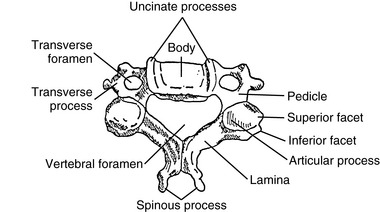
The functional unit of the spine, the motion segment, is the smallest component capable of performing the characteristic roles of the spine. The motion segment consists of two adjacent vertebrae and their associated structures. It is classically viewed as a three-joint complex, divided into anterior and posterior elements. The disc and vertebral bodies form the anterior joint and the two zygapophyseal joints form the posterior joints (Figure 5-1). The intervertebral joint is therefore a three-joint complex throughout the spine, except for the atlanto-occipital articulation. Changes affecting the posterior joints also affect the disc and vice versa.
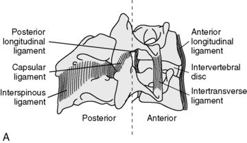
Two important ligaments help support the vertebral bodies. These are the anterior longitudinal ligament (ALL) and posterior longitudinal ligament (PLL) (see Figure 5-1). The ALL extends from the inner surface of the occiput to the sacrum. It starts as a narrow band that widens as it descends. It is thickest in the thoracic spine and thinnest in the cervical spine. The PLL runs from the occiput down the posterior portion of the vertebral bodies. It is a somewhat narrow structure that has lateral extensions and covers part of the IVD. It is also thickest in the thoracic spine and equally thin in the cervical and lumbar regions. In the lumbar spine, the PLL tapers, leaving the postero lateral borders of the disc uncovered and unprotected, with important clinical ramifications. Fibers from the PLL attach to the disc itself.
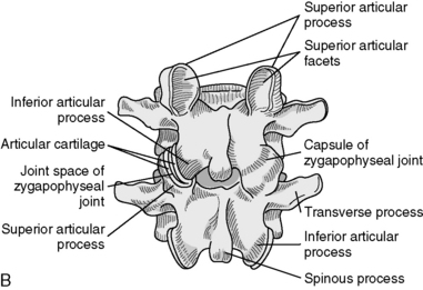
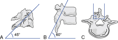
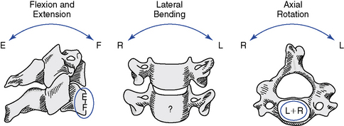
The articulations between the neural arches of vertebrae are diarthrodial joints (refered to as zygapophyseal joints, facet joints, or posterior joints). Each has a joint cavity enclosed within a joint capsule and lined with a synovial membrane (see Figure 5-1). The zygapophyseal joints are true synovial joints and form the posterior portion of the vertebral motion unit. They allow a guiding, gliding action, and the orientation of their joint surfaces is largely responsible for determining the amount and direction of regional spinal motions (Figure 5-2). Furthermore, the facet joints play a significant role in load-bearing. This varies between the facets and the disc, depending on the position of the spine. The facet joints bear an increasing percentage of the load as the spine moves toward an extended position.
Support and stability for the posterior joints come from the small segmental ligaments and the joint capsule (see Figure 5-1). The ligamentum flavum, a strong and highly elastic structure, connects adjacent lamina. The interspinous and supraspinous ligaments attach from spinous process to spinous process. Occasionally a bursa forms between these two ligaments. The intertransverse ligaments are relatively thin and run from transverse process to transverse process.
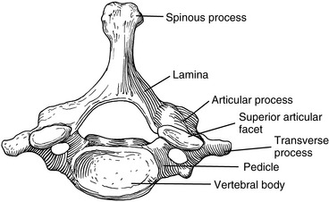
Although each region of the spine has its own unique characteristics, typical vertebrae have common descriptive parts that include a vertebral body, two pedicles, two lamina, four articular processes, two transverse processes, and a spinous process (Figure 5-3). There are in each region, however, atypical vertebrae, which either lack one of these descriptive features or contain other special peculiarities. The atypical vertebrae are C1, C2, C7, T1, T9 to T12, L5, and the sacrum and coccyx. Specific anatomic descriptions and functional characteristics are covered under each specific spinal region.
Evaluation of spinal joint function
Spinal joint scan
The scanning examination of the spine is designed to screen for alterations in structure or function indicative of possible joint subluxation/dysfunction syndromes. It incorporates the assessment of posture, global range of motion (ROM), mobility, and the location of any sites of palpatory pain (Box 5-1).
BOX 5-1 Physical Scanning Evaluation for Joint Dysfunction
Global range of motion
Posture Scan
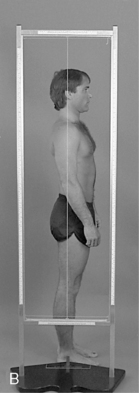
On the lateral analysis, visible surface landmarks that ideally coincide with a plumb line are the lobe of the ear, shoulder joint, greater trochanter, and a point slightly anterior to the middle of the knee joint and just anterior to the lateral malleolus (Figure 5-4).
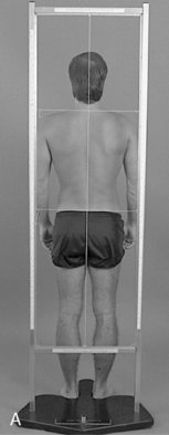
On posterior postural examination, the plumb line should pass through the external occipital protuberance, the spinous processes, the gluteal crease, midway between the knees, and midway between the ankles (see Figure 5-4). Look for specific postural faults, including head tilt, head rotation, shoulder unveiling, lateral curves of the spine, pelvic unleveling, and pelvic rotation. Postural faults that are suspected of having a muscular basis should be followed up with evaluations of muscle length, strength, and volume. Although there is no single ideal posture for all individuals, the best posture for each person is the one in which the least expenditure of energy occurs because the body segments are balanced in the position of least strain and maximal support.
Pain Scan
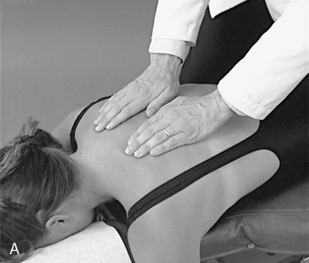
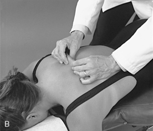
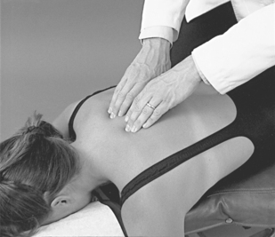
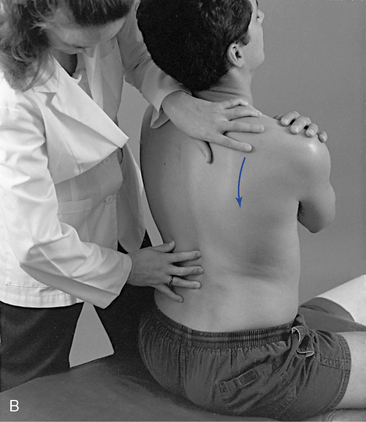
The pain scan is designed to screen for sites of possible abnormal bony or soft tissue tenderness. The superficial soft tissues are assessed with light contacts through the palmar surfaces of the fingers (Figure 5-5, A) or by rolling the superficial layer between the fingers and thumbs (Figure 5-5, B). The deeper paraspinal tissues are evaluated with the same palmar contacts, but more pressure is applied to explore the deeper layer (Figure 5-6). Particular attention is directed to identifying any tenderness in the soft tissues over the posterior joints.
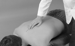
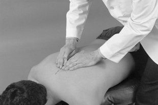
For evaluation of midline bony structures, the spinous processes and interspinous spaces may be scanned with the fingertips of one or both hands. When using a single-hand contact, the doctor rests the middle finger in the interspinous space and the index and ring finger on each side of the spinous process, spanning the interspinous space (Figure 5-7). The middle finger palpates for interspinous spacing and tenderness, and the index and ring fingers palpate for interspinous alignment and lateral spinous tenderness. When the fingers of both hands are applied, the fingertips meet at the midline to palpate interspinous alignment and tenderness (Figure 5-8).
Motion Scan
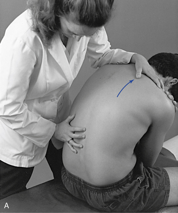
When evaluating sitting JP, the doctor sits or stands behind the patient and places the nonpalpating arm across the patient’s shoulders (Figure 5-9) or under the patient’s flexed arms. The flexed-arm position is commonly used in the middle to upper thoracic spine and is developed by having the patient interlace his or her fingers behind the neck (Figure 5-10). In the cervical spine, the indifferent hand (IH) supports the crown of the patient’s head (Figure 5-11).
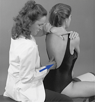
 Figure 5-9
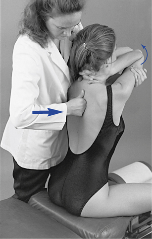
 Figure 5-10
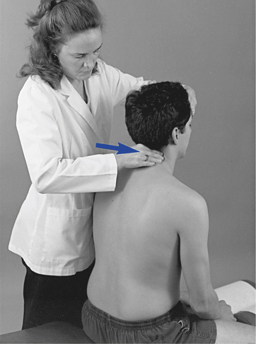
 Figure 5-11
With the patient prone, the doctor establishes bilateral contacts on each side of the spine or a reinforced contact over the spinous processes (Figure 5-12). To scan the spine, slide up or down, applying gentle posterior-to-anterior (P-A) springing movements. Regions of induced pain or inappropriate movement should be noted for further evaluation.
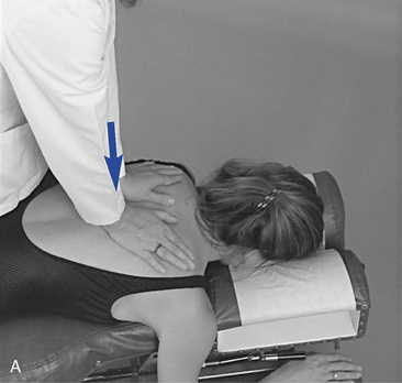
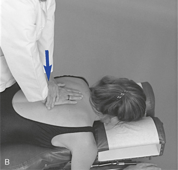
 Figure 5-12
To screen sections of the spine for possible movement restriction, place the patient in the sitting position, with the arms crossed over the chest. The doctor may either sit behind the patient or stand at the patient’s side (Figure 5-13). Trunk movement is controlled by establishing contacts across the patient’s shoulder or by reaching around to grasp the patient’s forearm. Cervical movement is directed by establishing a contact on the crown of the patient’s head or forehead (Figure 5-14). These procedures are not designed to assess JP; rather, they are applied to evaluate full ROM with overpressure. Palpation contacts are established with the fingertips, palm, or thenar surface of the doctor’s palpation hand. The contacts should be broadly placed so that movement at two to three motion segments may be scanned together.
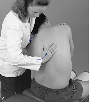
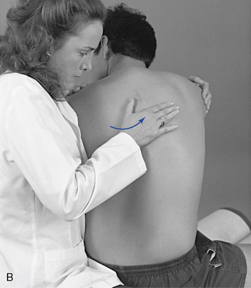
 Figure 5-13
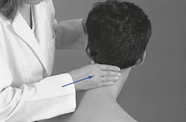
For lateral flexion and rotation assessment of the lumbar or thoracic region, contacts are established on the lateral surface of the spinous processes on the side of induced rotation or laterally bending (see Figure 5-13). In the cervical spine, the fingertips establish the contacts over the articular pillars (see Figure 5-14). For spinal flexion and extension, the contacts are established with the dorsum of the hand or fingertip contacts over the interspinous spaces of several adjacent segments (Figure 5-15). To evaluate movement, guide the patient through the full ROM and induce gentle overpressure at end range. During the assessment, any regional sites of elicited pain or perceived increased or decreased resistance should be noted. JP and regional motion scanning of the cervical spine are commonly performed in a supine position.
Identification of joint subluxation/dysfunction syndrome
As stated previously, the goal of manual joint assessment procedures is to identify possible sites of motion segment dysfunction. Many of the procedures used to scan the spine are also applied in the investigation and localization of dysfunction (Box 5-2). However, they are applied within a different context to identify more precisely the site and nature of the dysfunction/subluxation syndrome under question. They incorporate the detailed exploration of painful sites; the assessment of joint alignment and the texture, tone, and consistency of associated soft tissues; and the precise evaluation of intersegmental movements and end play. The evaluation of painful tissues often incorporates the application of various directions of applied pressure to determine the directions of painful movement. These procedures are referred to as joint challenging or joint provocation testing.
BOX 5-2 Isolation of Motion Segment Dysfunction (PARTS)
Goal
Neither scanning (see Box 5-1) nor isolation evaluation, alone or in combination, constitutes a complete examination. The doctor of chiropractic must be competent in performing a complete physical evaluation to assess the nature of the patient’s condition and to determine if the patient is suitable for chiropractic care.
Although all of the physical examination procedures discussed are an integral part of joint evaluation, it must not be forgotten that all have limitations. Many are based on the evaluation of symmetry in structure and function, and the degree of variation necessary to produce disease or dysfunction has not been determined. Asymmetry of structure and function is common, and minor abnormalities in alignment and motion may be within the range of normal variation. Furthermore, physical joint examination procedures depend on the skill of the examiner and are susceptible to errors in performance or interpretation. As discussed in Chapters 3 and 4 the present ability to precisely identify and adjust a single spinal segment may be limited and not directly related to clinical outcome. Based on this information, some have suggested that clinicians should focus on identifying regional sites (several segments) of dysfunction.1 2 3 4 It must also be remembered that the identification of dysfunction does not necessarily identify the cause.
Cervical spine
Functional anatomy of the upper cervical spine
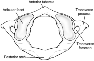
The atlas has no vertebral body or spinous process (Figure 5-16). It consists of a bony oval, with the two lateral masses connected by the anterior and posterior arches. The lateral masses, formed from enlarged pedicles, have concave articular facets superiorly for articulation with the occipital condyles and circular inferior facets for articulation with the axis.
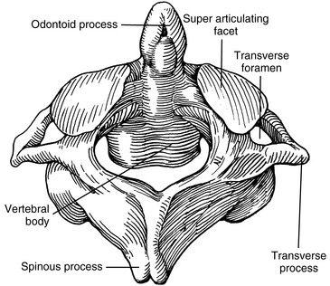
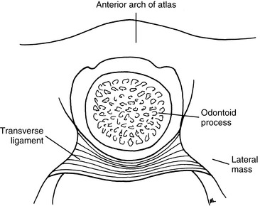
The outstanding feature of the axis (C2) is the presence of the odontoid process (dens) (Figure 5-17). The odontoid is formed by the fusion of the embryologic remnants of the vertebral body of the atlas to the superior aspect of the body of the axis. The spinous process of the axis is large and bifid, and it is the first palpable midline structure below the occiput. The superior articular surfaces project from the superior aspect of the pedicles to meet the inferior aspects of the atlas’ lateral masses. Their surfaces are convex and lie in the transverse plane, with a slight downward lateral slant. The atlantoaxial articulation is formed by articular surfaces of the C1–2 lateral masses. Both articular surfaces are convex, allowing for considerable mobility in rotation. The atlanto-odontal articulation is formed by the anterior arch of the atlas and the odontoid process. The odontoid process is completely surrounded by the anterior arch of the atlas anteriorly, the lateral masses laterally, and the transverse ligament posteriorly (Figure 5-18). It is a trochoid joint, providing a pivot action.
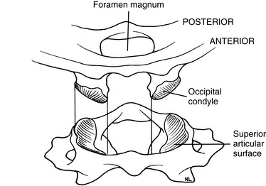
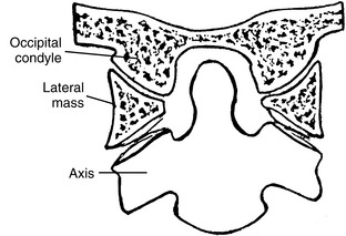
The atlanto-occipital articulation is a freely movable synovial condyloid articulation (Figures 5-19 and 5-20). The articular surfaces of the condyles are convex and converge anteriorly, resembling curved wedges that fit into matching concave surfaces in the lateral masses of the atlas. Individual axes for each condyle exist, demonstrating that there is no single axis for axial rotation. The axis of movement for rotation occurs at two points (eccentrically located), thus resulting in very little active rotation. Each condyle can move a degree or two forward and backward without the other side moving much.
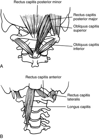
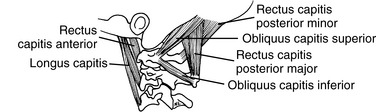
The muscles that provide the forces necessary for movement, postural support, and primary stability of the upper cervical region include the rectus capitis posterior major, rectus capitis posterior minor, rectus capitis lateralis, rectus capitis anterior, superior oblique, and inferior oblique (Figures 5-21 and 5-22). All of these muscles are supplied with motor fibers from the first cervical nerve and proprioceptive and pain fibers via a communicating branch from the second cervical nerve.
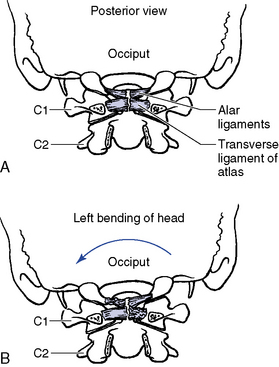
The ligaments that provide added stability to the upper cervical spine include the transverse ligament of the atlas, alar ligaments, PLL, posterior atlanto-occipital membrane, anterior atlantooccipital membrane, ligamentum nuchae, and the apical ligament (Figure 5-23). Because the ligaments of the upper cervical spine can be damaged by trauma, weakened by systemic inflammatory diseases, or congenitally absent or malformed, testing for their integrity should be done before manipulative therapy is begun. If instability is suspected, flexion-extension stress x-ray examinations should be performed.
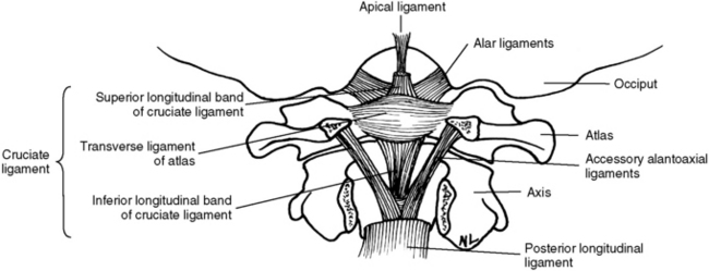
Figure 5-23 Upper cervical spinal ligaments shown with the posterior arch of the atlas and axis removed.
Range and Pattern of Motion of C0–C1
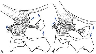
The principle movement that occurs in the atlanto-occipital articulation is flexion and extension.5 The combined range is approximately 25 degrees (Table 5-1 and Figure 5-24). Flexion and extension movements at C0–1 are predominantly angular movements in the sagittal plane, without any significant associated coupled motions. During flexion the occipital condyles glide posterosuperiorly on the lateral masses of the atlas as the occipital bone separates from the posterior arch. During extension, the condyles slide anteriorly on the lateral masses of the atlas while the occipital bone approximates the posterior arch of atlas (Figure 5-25).
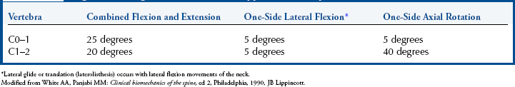
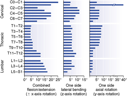
Figure 5-24 Representative values for rotatory range of motion at each level of the spine.
(From White AA, Panjabi MM: Clinical biomechanics of the spine, ed 2, Philadelphia, 1990, JB Lippincott.)
Axial rotation at the C0–1 articulation was previously thought to be very limited.6 However, recent studies have demonstrated a range of 4 to 8 degrees to each side.5 Rotational movement is limited by the articular anatomy and the connections of the alar ligaments. The movement that does occur is predominantly in the elastic range at the end of total cervical rotation, where it is usually coupled with some small degree of lateral flexion.7
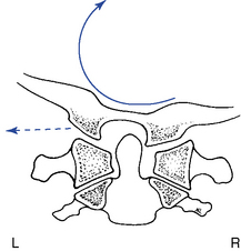
Lateral flexion of the atlanto-occipital articulation approximates that of axial rotation. Although the articular design of the atlanto-occipital articulation should allow for greater flexibility in lateral flexion, it appears that the attachments of the alar ligament function to limit this motion (Figure 5-26). Movement occurs primarily in the coronal plane, although it is typically associated with some small degree of coupled rotation in the opposite direction. This leads to rotation of the chin away from the side of lateral flexion. The predominant movements occurring at the articular surface during lateral flexion are coronal plane rotation (roll) and translation (slide). Roll and slide occur in opposite directions because of the convex shape of the occipital condyles and the concave shape of the atlas articular surface. Rotation (roll) occurs in the direction of lateral flexion, and translation (slide) occurs in the direction opposite the lateral flexion (Figure 5-27).
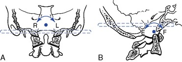
The instantaneous axes of rotation (IAR) have not been experimentally determined for the atlanto-occipital articulation. The axes were estimated “by determining the centers of the arches formed by the outline of the joints in the sagittal and frontal planes”5 (Figure 5-28).
Range and Pattern of Motion of C1–2
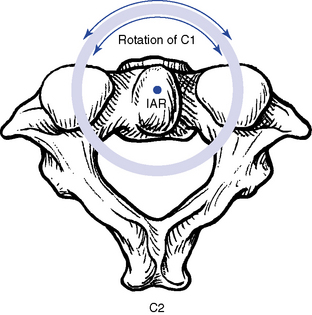
The principal movement that occurs at the atlantoaxial joint is axial rotation. Segmental range averages 40 degrees to each side, contributing to more than half of the total cervical rotation. The first 25 degrees of cervical rotation occur primarily in the atlantoaxial joint.7 During rotation the lateral mass and articular surface slide posteriorly on the side of rotation and anteriorly on the side opposite rotation. The motion occurs about a centrally located axis within the odontoid process (Figure 5-29). An additional subtle vertical displacement of the atlas takes place with rotation as a result of the biconvex structure of the articular surfaces (Figure 5-30).
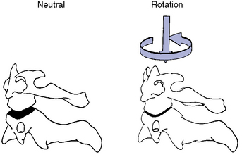
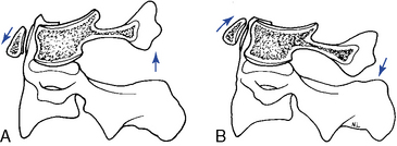
Flexion and extension movements of the atlas on the axis occur as rocking movements as a result of the biconvex facet surfaces. The IAR is located in the middle third of the dens. In flexion, the posterior joint capsule and posterior arches separate, and the atlas articular surface glides forward. In extension, the posterior joint capsule and posterior arches approximate, and the atlas articular surface glides posteriorly (Figure 5-31). Also, the anterior arch of the atlas must ride up the odontoid process during extension and down during flexion. Flexion and extension movements of the atlantoaxial joint are also associated with small translational movements from 2 to 3 mm in the adult up to 4.5 mm in the child.5 Any movement greater than these ranges should trigger an evaluation to assess the stability of the C1–2 articulation and the integrity of the odontoid and transverse ligaments.
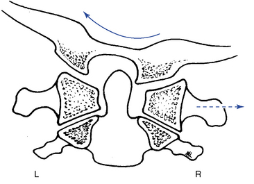
Compared with rotation, lateral flexion of the atlantoaxial articulation is limited, averaging approximately 5 degrees to each side.7 It has been suggested that lateral flexion is coupled with translation; however, this is a controversial subject.5 The associated translation is purported to occur toward the side of lateral flexion. In other words, right lateral flexion of the cervical spine would be associated with translation of C1 to the right (Figure 5-32).
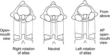
Further clouding the issue is the apparent translation that may be visible on an anterior-to-posterior open-mouth (APOM) radiograph with rotational subluxation of the atlas. Rotational movement of the lateral masses about the odontoid process may induce an apparent lateral translation of the atlas on the APOM radiograph as a result of projectional widening and narrowing of the lateral masses (Figure 5-33).
Functional anatomy of the lower cervical spine (C3–C7)
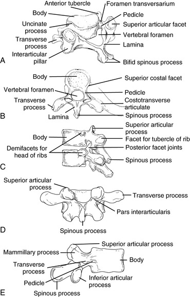
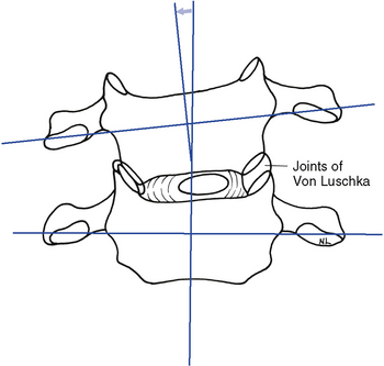
The typical cervical vertebrae (C3–C6) possess the same structural parts as all other true vertebrae, plus some unique and distinctive physical features (Figure 5-34). The spinous processes are bifid to allow for better ligamentous and muscular attachment. Each transverse process from C6 upward contains the transverse foramen, allowing for the passage of the vertebral artery. The body of the typical cervical vertebra has anterior and posterior surfaces that are small, oval, and wide transversely. The anterior and posterior surfaces are flat and of equal height. The posterior lateral aspect of the superior margin of the vertebral bodies is lipped, forming the uncinate processes, which serve to strengthen and stabilize the region. The uncovertebral articulations (joints of Von Luschka) are pseudojoints that have a synovial membrane with synovial fluid but no joint capsule (Figure 5-35). They serve as tracts that guide the motion of coupled rotation and lateral flexion. They begin to develop at 6 years of age and are complete by 18 years of age.
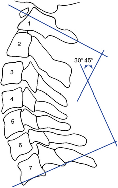
The articular facets are teardrop-shaped, with the superior facet facing up and posteriorly and the inferior facet facing down and anteriorly, placing the joint space at a 45-degree angle midway between the coronal and transverse planes (Figure 5-36). The disc height–to–body height ratio is greatest (2:5) in the cervical spine, therefore allowing for the greatest possible ROM (Figure 5-37).
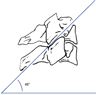
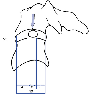
Figure 5-37 The location of the nucleus pulposus and the disc height–to–body height ratio in the cervical spine.
The C7 vertebra (vertebra prominence) is considered the atypical segment of the lower cervical spine. It demonstrates anatomic characteristics of both the cervical vertebra and the thoracic vertebra. It has a spinous process that is quite long and slender, with a tubercle on its end. The inferior articular processes are similar to those in the thoracic spine, and the superior processes match those of the typical cervical vertebra. C7 has no uncinate processes and no transverse foramen. The transverse processes are large, broad, and blunt. The transverse processes may become enlarged or develop cervical ribs, with the potential to create thoracic outlet compromise (Figure 5-38).
Cervical Curve
The cervical spine forms a lordotic curve that develops secondary to the response of upright posture. The functions of the cervical curve and the anterior-to-posterior (A-P) curves throughout the spine are to add resiliency to the spine in response to axial compression forces and to balance the center of gravity of the skull over the spine. The center of gravity for the skull lies anterior to the foramen magnum (Figure 5-39).
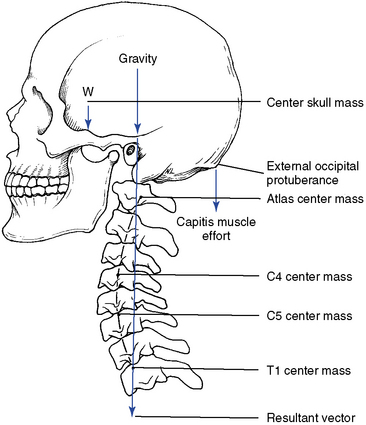
Figure 5-39 The center of gravity for the skull. If the cervical curve changes, the center of gravity shifts.
There are a number of opinions as to what the normal cervical curve should be and how it should be measured.6,8 9 10 11 12 13 14 There is also significant debate on what constitutes an abnormal curve and what biomechanical consequences, if any, will result from alteration in the cervical lordotic curve. A reduced cervical curve (hypolordosis) has the potential to shift more weight onto the vertebral bodies and discs and increase muscular effort as the posterior neck muscles work to maintain head position and spinal stability. An increased cervical curve (hyperlordosis) will potentially increase the compressive load on the facets and posterior elements (Figure 5-40).
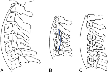
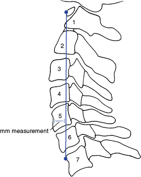
Various methods for radiographically measuring lordosis have been suggested. The most common method involves direct measurement of the curve by forming an angle between a line extending through the center of C1, with a line drawn along the inferior endplate of C7 (Figure 5-41). Although the cervical lordosis apparently extends to the T1–2 motion segment, measurements commonly use the C7 level as the lowest point reliably viewed on a lateral cervical x-ray film. Another method presented by Jochumsen12 proposes classifying the cervical curve by measuring the distance from the anterior body of C5 to a line running from the anterior arch of the atlas to the anterior superior aspect of the body of C7 (Figure 5-42). There is some agreement that the cervical curve midpoint is the C5 vertebra (C4–5 interspace).
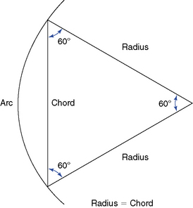
The proposed optimal curve for the cervical spine can be extrapolated from the mechanical principle that states the strongest and most resilient curve is an arc that has a radius of curvature equal to the cord across the arc (Figure 5-43). The length of the radius, and hence the cord, should equal approximately 7 inches or 17 cm. As the radius increases, the curve increases (flattens, as in hypolordosis) and vice versa.
Range and Pattern of Motion of the Lower Cervical Spine
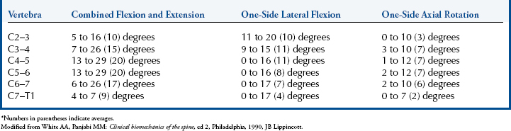
The lower cervical spine exhibits its greatest flexibility during flexion and extension movements (Table 5-2; see Figure 5-24). Lateral flexion exhibits slightly greater movement than rotation. Both rotation and lateral flexion decrease significantly at the thoracocervical junction.
Flexion and Extension
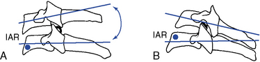
Movement averages approximately 15 degrees of combined flexion and extension per segment and is greatest at the C5–6 motion segment.15 Flexion and extension occur around an axis located in the subjacent vertebra and combine sagittal plane rotation with sagittal plane translation (Figure 5-44). This pattern of combined segmental angular tipping and gliding develops a stairstep effect, which is noted on flexion and extension radiographs.
With flexion, the articular joint surfaces slide apart, producing stretching of the facet joints and posterior disc and anterior disc approximation and compression. With extension, the opposite occurs. The disc is subjected to compression on the concave side and tension on the convex side. The side of the disc subjected to tension retracts and the side subjected to compression bulges.5 The net effect of these two opposing forces is to limit shifting of the nucleus pulposus during movements of flexion and extension and lateral flexion (Figure 5-45). Krag and colleagues16 implanted small metal markers within the lumbar and thoracic IVDs and confirmed the bulging and retraction of the discs during lumbar segmental flexion movements. However, they did note some minor posterior migration of the nucleus that was not identified by previous mathematical models. This phenomenon has not been investigated for the cervical spine.
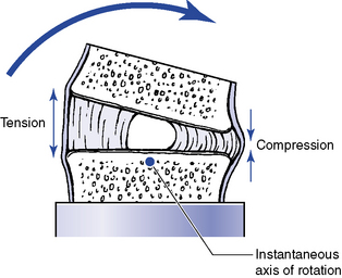
Figure 5-45 Representation of changes in the disc with flexion, as well as extension, or lateral flexion movements.
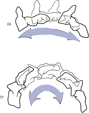
The coupled translation that occurs with flexion and extension has been measured at approximately 2 mm per segment, with an upper range of 2.7 mm.17 Translational movements do not occur evenly throughout the cervical spine.15 For every degree of sagittal plane rotation, more translation occurs in the upper cervical segments than in the lower cervical segments. This leads to a flatter arch of movement in the upper cervical spine (Figure 5-46). Accounting for radiographic magnification, White and Panjabi5 have recommended 3.5 mm as the upper end of normal translational movement in the lower cervical segments. Translation beyond 3.5 mm suggests end range segmental instability.
Lateral Flexion
Lateral flexion averages approximately 10 degrees to each side in the midcervical segments, with decreasing flexibility in the caudal segments. The IAR for lateral flexion has not been determined. Speculation places the axis in the center of the subjacent vertebral body (Figure 5-47).


Stay updated, free articles. Join our Telegram channel

Full access? Get Clinical Tree


