Stepwise Approach to Transosseous Wire and Half-pin Insertion and Tensioning
Paul S. Cooper
Introduction
Circular external fixation wires and half-pins are the primary methods of connection between the external fixator and the bone. Transosseous wires range from 1.5 to 1.8 mm in thickness have either a bayonet point or a drill tip and they come in either smooth or olive configurations. Olive wires, enhance buttress strength, are more stable than smooth wires and counteract deforming muscle forces especially with limb lengthening. Transosseous wires may be tensioned from 50 to 90 kg of force on open rings or posts and up to a maximum of 130 kg of force on a fully enclosed ring. With the variety of fixation clamps and methods, transosseous wires may be inserted in virtually any axis off any plane to secure on a ring or a series of rings.
Half-pins range between 4 and 6 mm in diameter, do not require tensioning and generally add greater stiffness to the external fixation construct. Half-pin tips range from self-drilling to blunted, cortical and cancellous, and may have hydroxyapatite or silver coating for bone in-growth or antibacterial activity, respectively. However, half-pins are more limited in orientation insertion.
Transosseous Wire Insertion and Fixation
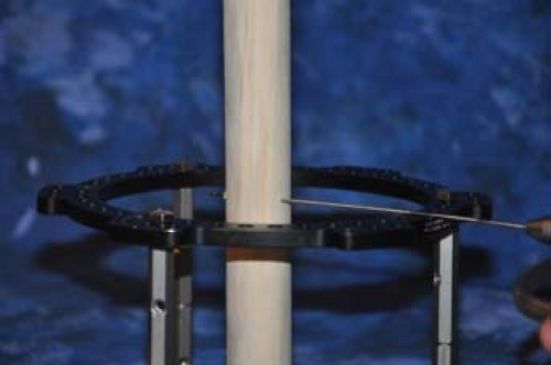
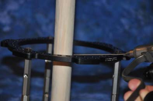
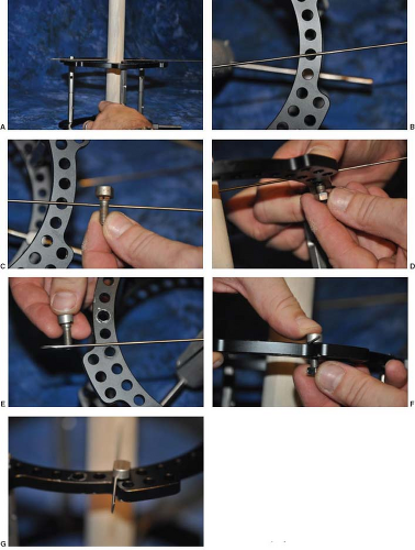
The standard smooth transosseous wire is typically drilled percutaneously off the ring to be attached. It is important with wire insertion to direct the wire gently without pressure on the ring (Figure 6.1). If too much pressure is applied, the wire is directed off the ring proximally and will not land at the same level at the opposite ring side for attachment (Figure 6.2). Conversely, if the wire is lifted off the ring, the end of the wire will be distally directed (Figure 6.3). A transosseous wire with incorrect alignment on the ring will serve to create uneven forces and undesired displacement of the bone segment when tensioned. The wire should be advanced sufficiently that the
farthest end has a minimum of two to three finger’s breadth of length beyond the ring, and then secured to the ring using either a central or an offset wire fixation bolt (Figure 6.4A–G).
farthest end has a minimum of two to three finger’s breadth of length beyond the ring, and then secured to the ring using either a central or an offset wire fixation bolt (Figure 6.4A–G).
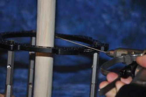 Figure 6.2. When too much pressure is applied to the inserted wire, it will be reflected proximally and will not land at the same level at the opposite ring side for attachment. |
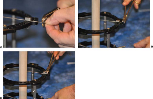
The transosseous wire is secured by the fixation bolt with a 10 mm crescent wrench and a slotted counter-rotation wrench to avoid displacement of the wire during tightening (Figure 6.5A and B). Once secured on the ring, the tip of the wire is cut and the wire is then curled on to the side of the ring with the end buried into one of the adjacent ring holes to avoid injury (Figure 6.6A–C). Next, the tensioned side of the wire is secured with
a similar fixation bolt and tensioned to a maximum of 130 kg against the ring when fully closed (Figure 6.7). If the ring is a 5/8 ring or open in any way, the maximum tension is 90 kg. Once tensioned to the desired amount, the fixation bolt is secured with the same method of a crescent wrench and counter-rotation wrench again, to avoid distortion of the straight line of the wire on the ring (Figure 6.8A–E). In conditions where the wire fixation does not permit direct seating of the tensiometer, a standoff threaded socket or rancho cube is used to apply the tension into the transosseous wire. In situations where there is insufficient length of wire for the tensiometer to capture, a method of in situ manual tensioning can be utilized. In this case, as the socket wrench is tightening the bolt on the underside of the ring, the fixation bolt is twisted clockwise up to 90 degrees, tightening the captured transosseous wire (Figure 6.9A–C). Amount of tension, although not quantified, is dictated by how much the bolt is rotated as it is tightened.
a similar fixation bolt and tensioned to a maximum of 130 kg against the ring when fully closed (Figure 6.7). If the ring is a 5/8 ring or open in any way, the maximum tension is 90 kg. Once tensioned to the desired amount, the fixation bolt is secured with the same method of a crescent wrench and counter-rotation wrench again, to avoid distortion of the straight line of the wire on the ring (Figure 6.8A–E). In conditions where the wire fixation does not permit direct seating of the tensiometer, a standoff threaded socket or rancho cube is used to apply the tension into the transosseous wire. In situations where there is insufficient length of wire for the tensiometer to capture, a method of in situ manual tensioning can be utilized. In this case, as the socket wrench is tightening the bolt on the underside of the ring, the fixation bolt is twisted clockwise up to 90 degrees, tightening the captured transosseous wire (Figure 6.9A–C). Amount of tension, although not quantified, is dictated by how much the bolt is rotated as it is tightened.
Optimal stability of the ring segment consists of maximum transosseous wire spread ideally at 90 degrees, and separation of the wires off the ring in all planes. Stability in foot and ankle
circular external fixators follows the rule of twos: Two limb segments, two levels of fixation per segment, and two wires per level of fixation. This means that on the same side of the ring, the two transosseous wires should be diverging as close to 90 degrees as soft tissue allows. In addition, transosseous wires should be separated on opposite sides of the ring to allow for additional distance between the two wires (Figure 6.10).
circular external fixators follows the rule of twos: Two limb segments, two levels of fixation per segment, and two wires per level of fixation. This means that on the same side of the ring, the two transosseous wires should be diverging as close to 90 degrees as soft tissue allows. In addition, transosseous wires should be separated on opposite sides of the ring to allow for additional distance between the two wires (Figure 6.10).
 Figure 6.5. The transosseous wire is secured by the fixation bolt with a 10 mm crescent wrench (A) and a slotted counter-rotation wrench to avoid displacement of the wire during tightening (B). |
There are several methods available to achieve optimal distance between wires. The simplest is to place the second wire on the opposite side of the ring. This minimizes one wire hitting and deflecting off the other. A common method for slight spacing off the ring is to use a longer fixation bolt with two 4 mm washers (Figure 6.11). This has the advantage of simplicity with fixation and tensioning but will require a threaded socket to tension. For greater distances off the ring, a male one-, two-, three-, or four-hole post may be used with the fixation bolt attached to the post. This allows not only greater distance for the wire off the ring but also allows for multiple degrees of
freedom in wire placement that standard fixation bolt does not permit (Figure 6.12A–J). Caution should be noted that as the transosseous wire is placed further off the ring that the maximum amount of tensioning diminishes and a bowing effect may be created (Figure 6.13). Maximum tensioning off a post may usually not exceed 90 kg of force.
freedom in wire placement that standard fixation bolt does not permit (Figure 6.12A–J). Caution should be noted that as the transosseous wire is placed further off the ring that the maximum amount of tensioning diminishes and a bowing effect may be created (Figure 6.13). Maximum tensioning off a post may usually not exceed 90 kg of force.
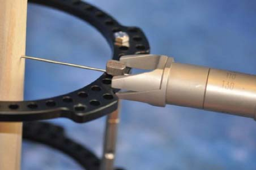 Figure 6.7. Example of a tensiometer used to tension the tibia transosseous wire at approximately 130 kg of force. Tibial, calcaneal, and forefoot transosseous wires are usually tensioned in various amounts and according to the overall external fixation construct, surgical correction, and patient’s condition.
Stay updated, free articles. Join our Telegram channel
Full access? Get Clinical Tree
 Get Clinical Tree app for offline access

|
