Stepwise Approach to Ankle Elective and Reconstructive Surgery with External Fixation
Paul S. Cooper
Introduction
Management of intermediate to advanced stage ankle osteoarthritis has evolved over the past decades incorporating the use of circular or uniplane monolateral external fixators. Focal areas of intermediate stage ankle osteoarthritis may be addressed through realignment techniques using a supramalleolar osteotomy (SMO). Adapted from the concepts of high-tibial osteotomies, this technique is used to shift the pressure off a focal region of chondral wear to more healthy zones of the ankle joint. In cases of prior malunion from trauma or growth plate disturbance, the SMO is used to restore the normal tibial articular surface angles. In cases of global involvement, or associated severe ankle ankylosis, arthrodiastasis may be an effective preemptive procedure prior to salvage options including arthroplasty or arthrodesis. The technique of ankle arthrodiastasis involves gradual joint distraction of between 5 and 10 mm to allow for healing of a symptomatic intermediate stage arthritic ankle joint. Although the exact mechanism of action is unclear, intermittent hydrostatic pressure combined with off-loading the ankle joint has been proposed. While long-term outcomes are unknown, the short-term benefits may require 1 to 2 years to be fully appreciated by the patient. For end-stage ankle arthritis, ankle arthrodesis remains an effective salvage solution in the foot and ankle.
Indications/Contraindications
Conventional methods include internal screws, plating, or retrograde intramedullary nailing. In cases with poor skin quality, the requisite extensile exposure for internal fixation may yield an unacceptable high rate of wound complications. Severe ankle deformities may also not be amenable to acute full correction in the operating room from neurovascular compromise. Poor bone quality can necessitate extensive internal fixation constructs, requiring additional exposure. Furthermore, optimal compression across the arthrodesis site may not be obtained at the time of the index procedure. External fixation can address these issues through the use of gradual and continuous compression over an extended period of time till the desired alignment and compression is achieved for successful bony union. External fixation use for these methods has the added advantage of minimizing soft tissue dissection for exposure to achieve the desired goals and can even be performed percutaneously in severe dysvascular cases.
Detailed Surgical Technique
Circular External Fixation for Ankle Arthrodesis
Ankle arthrodesis utilizing circular external fixation has been a powerful method for difficult ankle arthrodesis conditions. These include nonunions from methods of internal fixation, pyarthrosis of the ankle joint with associated osteomyelitis, extensive compromised soft envelope surrounding the ankle joint, posttraumatic ankle arthrosis with avascular necrosis, and neuropathic-mediated deformities. Unlike conventional methods of internal fixation, external fixation allows for continued application of compression across the ankle joint in the postoperative period, thus improving union rates. Furthermore, in cases where soft tissue may be compromised with conventional exposures or active ulcerations, external fixation permits full access to the soft tissues permitting monitoring in the postoperative period. In cases where bone is of poor quality with potential loss of internal fixation postoperatively resulting in nonunion, external fixation with multiple points of fixation allows for enhanced stability regardless of bone quality.
A standard static circular external fixator may be pre-built in the majority of cases and consists of a tibial block
comprising two 155 mm rings or alternatively 180 mm rings in larger lower extremities. These may be connected with either stacked threaded sockets or alternatively threaded rods. A standard external foot plate of the same diameter to that of the tibial ring is used in combination with a half ring attached at 90-degree orientation which closes the foot ring and permits maximum wire tensioning as well as additional points of fixation. In uncomplicated cases, threaded rods may be used to join the segments and serve as a simple method of axial compression with the use of compression–distraction nuts (Figures 15.1–15.3). Four equal-size length threaded rods have one set of nuts on both sides of the threaded rods at equal distances (Figure 15.4). The threaded rods are equally spaced around the foot ring and secured to the corresponding holes on the tibial ring using conventional nuts and on the bottom of the foot plate using compression–distraction nuts (Figures 15.5–15.8). Compression occurs from clockwise turning of the compression nut against the foot plate while simultaneously unlocking the nut on the opposite side. Unlike in bone transport technique, the compression amount and frequency can be applied as desired.
comprising two 155 mm rings or alternatively 180 mm rings in larger lower extremities. These may be connected with either stacked threaded sockets or alternatively threaded rods. A standard external foot plate of the same diameter to that of the tibial ring is used in combination with a half ring attached at 90-degree orientation which closes the foot ring and permits maximum wire tensioning as well as additional points of fixation. In uncomplicated cases, threaded rods may be used to join the segments and serve as a simple method of axial compression with the use of compression–distraction nuts (Figures 15.1–15.3). Four equal-size length threaded rods have one set of nuts on both sides of the threaded rods at equal distances (Figure 15.4). The threaded rods are equally spaced around the foot ring and secured to the corresponding holes on the tibial ring using conventional nuts and on the bottom of the foot plate using compression–distraction nuts (Figures 15.5–15.8). Compression occurs from clockwise turning of the compression nut against the foot plate while simultaneously unlocking the nut on the opposite side. Unlike in bone transport technique, the compression amount and frequency can be applied as desired.
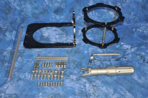 Figure 15.1. Basic circular external fixation components for ankle arthrodesis. Threaded rods are used to connect and compress between the tibial block and the foot plate. |
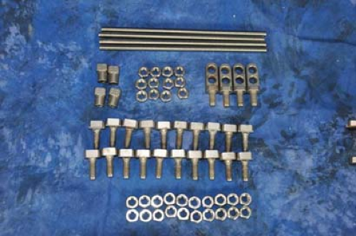 Figure 15.2. Close-up view demonstrating the use of threaded rods, four compression nuts, two-hole male posts, and fixation bolts with corresponding nuts. |
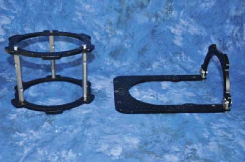 Figure 15.3. Basic external fixation components consisting of the tibial block and the foot plate. |
Ankle joint preparation consists of preparation of the tibiotalar joint surfaces. This entails minimally denuding the tibial plafond in addition to the talar surfaces with either a high-speed burr, curettage, or sagittal saw. All ankle joint sclerotic or avascular regions need to be either fully resected or perforated to create bleeding channels. The medial gutter should similarly be resected; however, the medial malleolus should be preserved to increased bone contact for stability with the arthrodesis in addition to vascular preservation through the deltoid ligaments (Figures 15.9–15.11). One to two threaded Steinmann pins are used to temporarily stabilize across the tibiotalar surface in the optimal position desired. Typically, this consists of the talus being translated posteriorly on the tibia combined with slight external rotation compared to the contralateral side, slight valgus, and neutral dorsiflexion and plantarflexion position (Figure 15.12).
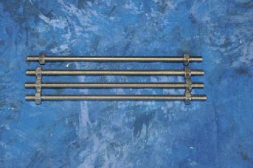 Figure 15.4. Threaded rods of equal length threaded with nuts on both sides. |
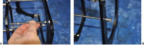 Figure 15.5. Threaded rods are aligned to identical corresponding holes between the distal tibial ring and the foot plate (A). Failure to properly align may result in jamming or displacement during compression. Close-up view of the compression nut on the distal end of the foot plate (B). |
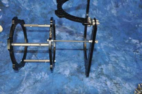 Figure 15.6. Connection of the tibial block to the foot plate with threaded rods. Upper end of threaded rod is secured with nuts on both sides of the distal tibial ring, where the lower side of the threaded rod has the compression nut distally for controlled compression across the ankle joint. |
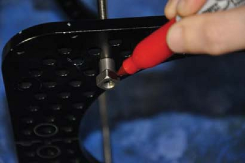 Figure 15.7. If planned compression is to occur, marking one face of the compression nut will ease in determining a full rotation. |
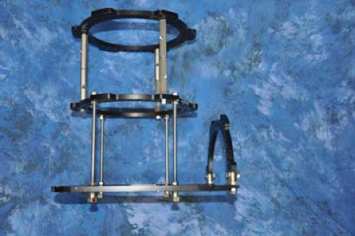 Figure 15.8. Finished pre-built circular external fixator for ankle arthrodesis. |
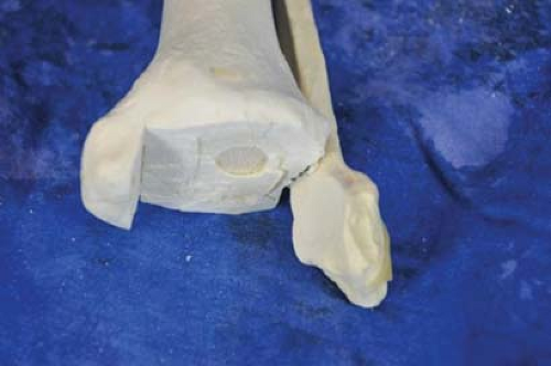 Figure 15.9. Preparation of tibia for ankle arthrodesis. Note preservation of medial malleolus. |
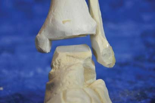 Figure 15.10. Talar preparation for ankle arthrodesis. |
The pre-built static circular external fixator is slid over the stabilized ankle and positioned such that the foot plate is parallel with the subtalar joint which externally is represented by the junction of the glabrous skin on the plantar foot. Rolled-up sterile towels are used under both calcaneus and posterior calf on the proximal tibial ring in order to align and center the lower extremity within the circular external fixator (Figure 15.13). The first reference wire is inserted slightly oblique, directed anteromedial to posterolateral under the malleoli into the talar body. This avoids capturing either the medial malleolus or the fibula which would prevent compression through the ankle joint. The reference wire is usually tensioned between 110 and 130 kg of force. Overall alignment is checked with regard to the position of the calcaneus posteriorly and medial/laterally in the circular external fixator once the towels are removed (Figures 15.14 and 15.15). Ideally, there should be two fingers’ breadth minimum distance between the calcaneus and the posterior foot plate with the foot centered.
Once the distal position is deemed acceptable, a proximal reference wire is inserted off the proximal tibial ring and tensioned between 110 and 130 kg of force (Figure 15.16). There should be approximately two fingers’ breadth distance from the back of the anterior ring to the tibial crest. Most importantly is to confirm adequate posterior ring accommodations for the calf musculature. If the space is tight, either the tibia is anteriorly positioned to one finger’s breath from the front of the ring, or a larger ring is required. Once overall alignment is felt to be acceptable, any residual medial–lateral translation can be addressed by gently tapping on the circular external fixator opposite the direction to center the lower extremity (Figures 15.17 and 15.18). Following this, additional wires are inserted into the hindfoot including a second talar wire directed posteromedial to anterolateral underneath the medial malleolus to avoid capture of either malleoli, again
tensioned on the foot ring between 110 and 130 kg of force (Figure 15.19).
tensioned on the foot ring between 110 and 130 kg of force (Figure 15.19).
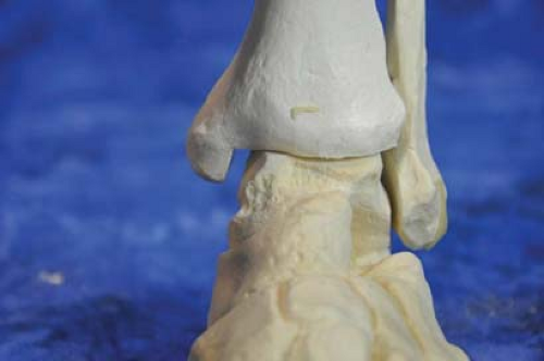 Figure 15.11. Note the apposition of the distal end of the tibia to the talar surface. |
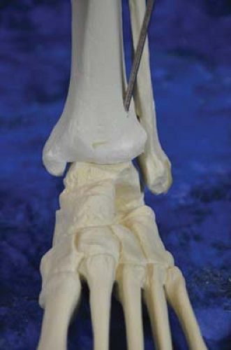 Figure 15.12. One or two Steinmann pin(s) is used for temporary fixation. |
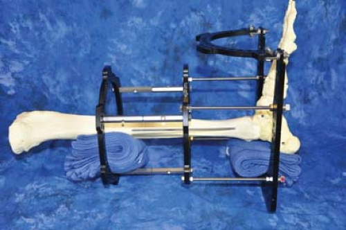 Figure 15.13. Alignment of the lower extremity in the circular fixator can be aided with the use of sterile towels in the operating room. Overall alignment is dictated by the foot plate position on the foot, which usually corresponds with the subtalar joint. |
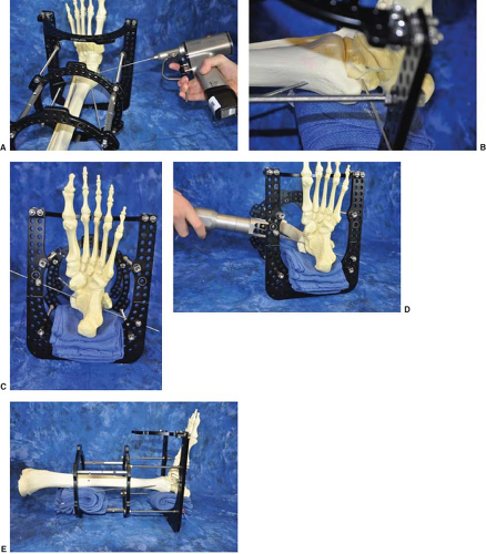 Figure 15.14. A reference transosseous wire is directed anteromedial to posterolateral below both malleoli (A). Note the transosseous wire positioned through the talar body (B). Reference transosseous wire position as viewed inferiorly (C). Tensioning of the reference transosseous wire between 110 and 130 kg of force (D). Position of the lower extremity is checked following tensioning of the reference transosseous wire for displacement (E). |
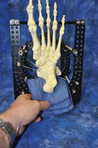 Figure 15.15. Surgical sterile towels may then be removed to confirm adequate space to the posterior aspect of the foot plate. |
Definitive tibia stabilization may be achieved with either one to two additional transosseous wires per ring on the segment or alternatively to use half-pins in a delta configuration to maximize half-pin spread and minimize risk for pathologic fracture upon external fixation removal (Figure 15.20). Additional transosseous wires may also be added into both the hindfoot and the midfoot/forefoot region for added stability and to minimize wire/pin irritation postoperatively. These transosseous wires may be directed into the midfoot or forefoot regions in an oblique pattern with divergence to maximize stability (Figure 15.21). When definitive stability of the lower extremity is achieved, the threaded Steinmann pin(s) are removed and any shifting at the arthrodesis site is observed (Figure 15.22). Compression is then achieved by loosening the opposite nut to that of the compression–distraction nut and advancing in a clockwise fashion proximally on the threaded rod to the desired degree of compression (Figure 15.23). The
degree of compression applied should be enough to visually identify additional bowing on the transosseous wires on the foot plate in clinical or C-arm fluoroscopic visualization and confirmation of joint obliteration. In osteoporotic conditions, additional fixation may be added to the calcaneus by using the drop-wire technique consisting of a two-hole male post being connected either to a smooth or to an olive transosseous wire in an oblique pattern (Figure 15.24 and Clinical Case I).
degree of compression applied should be enough to visually identify additional bowing on the transosseous wires on the foot plate in clinical or C-arm fluoroscopic visualization and confirmation of joint obliteration. In osteoporotic conditions, additional fixation may be added to the calcaneus by using the drop-wire technique consisting of a two-hole male post being connected either to a smooth or to an olive transosseous wire in an oblique pattern (Figure 15.24 and Clinical Case I).
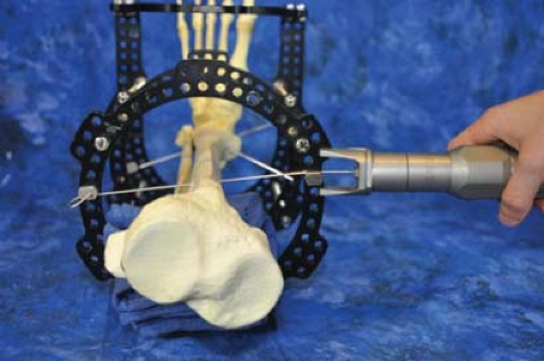 Figure 15.16. Proximal reference wire is directed transversely into the corresponding holes with the proximal tibial ring. |
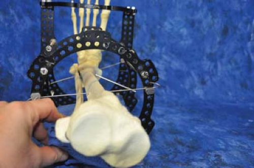 Figure 15.17. Removal of the leg surgical sterile towels and checking for clearance of soft tissues from the posterior aspect of both tibial rings. Ideally, the tibia should be located with one-third clearance anteriorly and two-thirds posteriorly within the ring(s). |
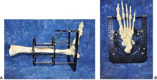 Figure 15.18. Optimal position with both proximal and distal reference transosseous wires placed and tensioned (A). Note central location of the foot and tibia in reference to the circular external fixation rings. This is the ideal time to make any fine adjustments if needed (B).
Related posts: History and Evolution of External Fixation History and Evolution of External Fixation
 Stepwise Approach to Static Circular External Fixation Stepwise Approach to Static Circular External Fixation
 Stepwise Approach to Midfoot and Hindfoot Elective and Reconstructive Surgery with External Fixation Stepwise Approach to Midfoot and Hindfoot Elective and Reconstructive Surgery with External Fixation
 Stepwise Approach to Forefoot Elective and Reconstructive Surgery with External Fixation Stepwise Approach to Forefoot Elective and Reconstructive Surgery with External Fixation
 Surgical Off-loading External Fixation and Plastic Reconstruction of the Foot and Ankle Surgical Off-loading External Fixation and Plastic Reconstruction of the Foot and Ankle
 Stepwise Approach to Bone Loss, Transport, and Lengthening with External Fixation Stepwise Approach to Bone Loss, Transport, and Lengthening with External Fixation
Stay updated, free articles. Join our Telegram channel
Full access? Get Clinical Tree
 Get Clinical Tree app for offline access

|