Safe Lower Extremity Anatomic Zones for External Fixation
Patrick R. Burns
Ryan L. McMillen
Introduction
The use of external fixation continues to grow and evolve in foot and ankle surgery. Understanding the basic principles of this fixation technique is paramount for improved outcomes. Similar to internal fixation, external has its own unique properties and the surgeon must have fundamental knowledge of basic external fixation principles. Without full understanding of the indications and mechanics—including types of external fixation devices, components, and application—the surgeon and his/her constructs will never reach their full potential.
As with any fixation technique, external fixation requires a thorough knowledge of indications, physical properties, constructs, and materials. Many decisions made before, during, and after surgery will affect outcomes. The surgeon should plan ahead when time permits, while being prepared with alternatives. There should be an idea of the type and style of external fixator that may best fit the situation and desired outcome.
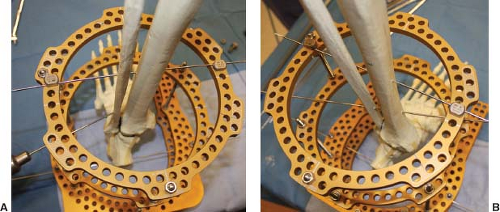
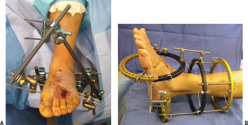 Figure 2.1. Examples of a standard “pin-to-bar” or “delta” configuration (A) and multiplanar (B) circular external fixation systems. |
Once the surgeon has learned principles of external fixation types, the different styles, the materials, the components, the basic physics, and biomechanics, the next step is applying that to pathology. As one begins to understand this form of fixation, the indications are endless in the lower extremity. Types of external fixators will be discussed elsewhere in this text, but the main types include pin-to-bar type (Figure 2.1A) predominantly utilized for temporary and traumatic conditions, and the multiplanar style (Figure 2.1B) which is generally utilized for deformity correction. Although safe anatomic zones are most important in the setting of the through-and-through wires of the circular external fixation systems, every external fixator must be applied with anatomic and biomechanic restrictions in mind.
The basic requirements for external fixation application include the fixator itself and a way to connect to the osseous structures of the patient. The workhorse for most circular external fixation systems is the transosseous fixation wire. Alternative names have been interchanged including “transfixation”
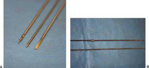
wires, “smooth” wires from the smooth stainless steel they are made, and “skinny” wires in comparison to the size of their half-pin counterparts made popular in the United States. Many modifications have followed through the years, including different diameters, tip constructs, and specializations such as offset enlargements to act as “olive” wires which will be discussed later (Figure 2.2A and B).
wires, “smooth” wires from the smooth stainless steel they are made, and “skinny” wires in comparison to the size of their half-pin counterparts made popular in the United States. Many modifications have followed through the years, including different diameters, tip constructs, and specializations such as offset enlargements to act as “olive” wires which will be discussed later (Figure 2.2A and B).
Traditional smooth wires in adult patients undergoing circular external fixation are either 1.8 or 2.0 mm. These are standard sizes for most industries providing circular external fixators. Over recent years, modifications have been made to the wire tip to aid in placement. This has become useful in particular for certain wires placed in the tibia. Its dense cortical bone can sometimes make placement difficult. Dull or blunt tips can cause the surgeon to apply increased pressure and use excessive drill times leading to overheating of the wire. Long term, the area of bone surrounding the wire may undergo necrosis leading to loosening of the wire and weakening of the overall external fixation construct. Along with tip modifications such as “X” or drill tips that allow easier wire placement, one may limit overheating by “pulsing” the wire during placement instead of drilling constant. Cooling the area during drilling with saline may also limit the effects of high temperatures. Too much heat along the skin, in particular the leading edge of the wire that has done the drilling can burn soft tissue. The tip becomes very hot and can burn the skin leading to irritation, drainage, and infection. When external fixation constructs consistently have multiple wires with erythema and drainage the first weeks following application, one must look at technique as a possible cause (Figure 2.3A and B). Simply addressing wire placement technique and the heat generated can minimize bone and skin thermal necrosis.
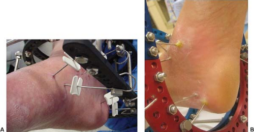 Figure 2.3. Examples of a stable external fixation construct with clean wire sites (A) and an external fixator with multiple locally infected wires typical of an unstable construct (B). |
In addition, it is important to review the other chapters in this text and be familiar with the general principles of external fixation. One must have knowledge of the strengths and weaknesses of external fixation, along with the indications and limitations. For improved outcomes, the surgeon must have knowledge about the available components and how to increase strength and stability to avoid any potential complications. This chapter is intended to give an overview of anatomic safe zones so these principles and components can be physically applied. Without proper knowledge of lower extremity anatomy, the external fixator and connecting elements can cause damage to vital structures. Using knowledge of anatomy and available topographic landmarks will help guide the transfixation wires in the safest place possible. It is important to note that there are no consistently safe zones, but there are less safe areas.
One must also realize that in applying the external fixator, you may not be able to satisfy every biomechanical principle. For example, the strongest construct for a ring mid-tibia would be two wires 90 degrees from each other but anatomic constraints will not permit that construct. A wire cannot be placed directed anteroposterior due to the gastrocnemius muscle. Instead, wires are placed at the largest angle permitted by anatomy.
Terminology
There is no single completely accepted method of describing wire placement with regard to external fixation about the foot and ankle. There are however some accepted terms allowing those in surgery and throughout disciplines to communicate. Most terminology revolves around anatomy for that particular segment. For example, a skinny wire placed posterior lateral from the fibula heading anterior medial through the tibia is typically termed a “fibular” wire because it goes through the fibula. This chapter will go through each zone of the leg, ankle, and foot in attempts to standardize these terms.
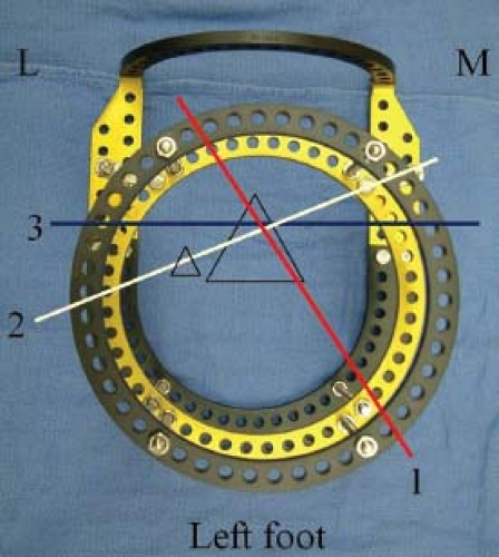
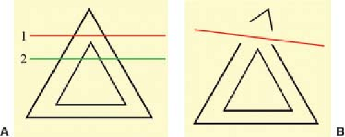
For placement of skinny wires in the tibia, nomenclature remains fairly consistent along its entire course. There are three main wires utilized on a regular basis. They are termed “axial,” “medial face,” and “fibular” wires (Figure 2.4). Axial wires are a workhorse for foot and ankle external fixation. This wire is typically driven across the anterior tibial crest, parallel with the weight bearing surface and perpendicular to the long axis of the tibia itself (Figure 2.5). When placing this wire, it is paramount that the wire catches a portion of the medullary space. If this wire is too superficial, it becomes unicortical and has the potential for fracture through the anterior tibial crest (Figure 2.6A and B).
The next wire is the fibular. As mentioned previously, it typically courses through both the fibula and tibia from a posterior lateral position to anterior medial (Figure 2.7 and BA). There is some debate as to whether or not to include the fibula, but if so desired, it is easiest to begin lateral, at the fibula itself. It is also easier to start at the smaller target and head toward the larger, allowing more room for error. If including the fibula is not crucial, one can begin perpendicular to the medial face of the tibia and head toward the fibula posterior lateral essentially giving the same outcome.
The final common tibial wire is the medial face. It is commonly given this term due to the fact that it is essentially parallel to the medial face of the tibia. It is driven from lateral to medial direction. The start point is on the lateral side of the
tibia, just lateral to the anterior crest. It is then driven posterior medial basically following and parallel to the medial face of the tibia (Figure 2.8). Issues with this wire tend to be irritation to the large posterior leg musculature.
tibia, just lateral to the anterior crest. It is then driven posterior medial basically following and parallel to the medial face of the tibia (Figure 2.8). Issues with this wire tend to be irritation to the large posterior leg musculature.
When it comes to the foot, terminology is less standard. Starting with the talus, an axial wire is one placed through the body or neck, parallel to the ankle joint, and will be discussed later. The calcaneus can be fixed with skinny wires through the posterior safe zone. An axial calcaneal skinny wire is placed parallel to axial wires in the leg. In the midfoot and forefoot, skinny wires tend to follow the normal anatomic arch if present. In some cases of pes planovalgus or Charcot deformity, there is no arch, but in more typical anatomy, the wires are angled from slightly plantar to dorsal. There is no standard nomenclature for these wires.
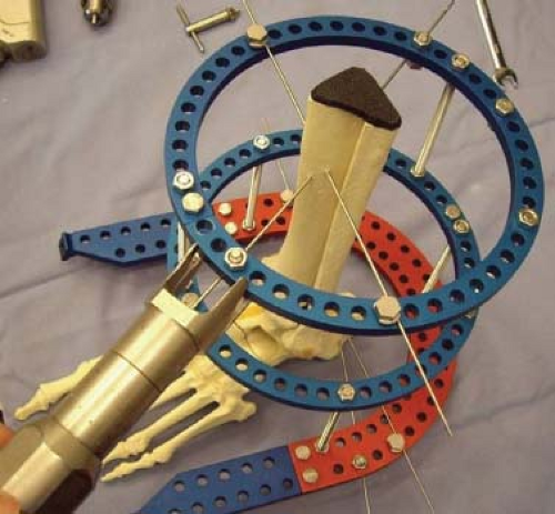
When applying the circular external fixation device, most surgeons try to apply the majority of the transosseous wires directly to the external fixator ring level and even. This minimizes connecting elements. Tensioned skinny wires will have their greatest strength when they are attached directly to the rings themselves. If wires are attached utilizing washers, posts, and extension plates, there is a loss of strength and stability. Having the wire connect directly to the external fixator may be optimal, but in some cases, cannot be achieved. Some applications require the wire to be in a certain orientation and the location of the external fixator is secondary. When the skinny wire is placed first, irrespective of the external fixator, it is termed “wires first” method (Figure 2.9). The circular external fixator is then “built up” to the pre-inserted wires. Common examples in the lower extremity are the midfoot
and forefoot where anatomy dictates the position of the wires. Here, wires are often connected to the external fixator with posts and washers. Another common example is fracture care where a particular fragment may need stability but does not correspond with the external fixator’s design.
and forefoot where anatomy dictates the position of the wires. Here, wires are often connected to the external fixator with posts and washers. Another common example is fracture care where a particular fragment may need stability but does not correspond with the external fixator’s design.
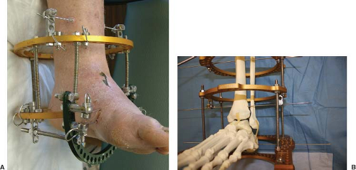 Figure 2.10. Example of a “drop wire” for added fixation. The wire is added either above (A) or below (B) an existing circular ring and attached with posts. |
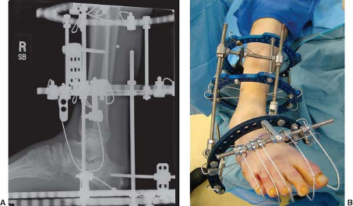
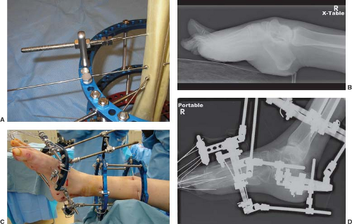
Other terms utilized include “drop wire,” “stirrup,” and “motor.” A drop wire is typically a third wire added to a circular ring for increased stability. The wire is dropped down on a post and driven in the typical manner as others for that anatomic area (Figure 2.10A and B). Stirrups are wires that basically hold position but not necessarily tensioned. They can be useful in areas such as holding a fracture fragment stable while manipulating the remaining pieces, or holding the position of the digits while moving the remainder of the foot and ankle are corrected so as not to increase their deformity (Figure 2.11A and B). Motors are typically threaded rods that compress or distract as they are manipulated with differing combinations of posts, wires, and nuts. There are many ways to construct a
motor and are not to be discussed here, but when the surgeon becomes comfortable and creative, it increases the external fixator’s usefulness (Figure 2.12A–D).
motor and are not to be discussed here, but when the surgeon becomes comfortable and creative, it increases the external fixator’s usefulness (Figure 2.12A–D).
Principles and Techniques for Transosseous Wire Application
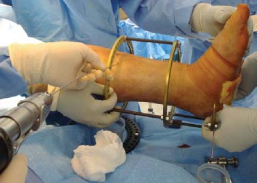
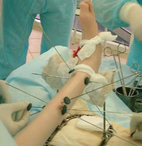
As discussed in the Introduction, the transosseous wire is the main component utilized to attach the external fixator to the patient’s bone. A general understanding of appropriate external fixation construct will help the surgeon apply appropriate techniques for wire application. To obtain maximum stability the smooth wires should be placed 90 degrees to each other. They also should be attached directly to the external fixation rings. The more extending elements added to the construct, the more likely there will be loosening and potential construct failure. It is usually helpful to have the external fixator pre-built so that it can be used as a guide while applying smooth wires. The leg can be placed in the external fixator, giving a general idea of position. The leg is placed slightly anterior in the circumference of the circular tibial ring block. This allows for clearance for the large posterior muscle group and for potential swelling. Sterile towels can be utilized to hold the leg in proper position while maintaining clearances. The skinny wires can then be applied. The wire is placed directly on the circular fixator ring, held in place with dampened gauze (Figure 2.13). This helps cool the wire and allows the surgeon to guide the wire without being entangled. The correct orientation is decided and the wire is driven straight through to the other side and then fixed to the circular fixator ring.
When inserting the wire, the surgeon should use the external fixator as a guide and slide the smooth wire to the area
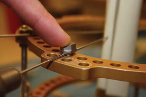
where they want to begin wire placement. Another technique involves a slotted bolt as a guide (Figure 2.14). This is a useful technique for the less experienced surgeon to keep the wire on the external fixator ring while inserting the wire. The skin should be pierced and knowledge of surface anatomy along with tactile sensation helps guide the wire in the desired orientation. As the surgeon drills the wire, it should be pulsed. This method helps decrease friction which leads to increased temperature of the wire. Once the second cortex has been breached, a mallet should be used to continue the smooth wire through the distal soft tissues and across the far end of the external fixator. Each smooth wire is then attached to the external fixator and tensioned appropriately. Smooth wires should always be placed from the anatomic location that is the most vulnerable to the area that is least vulnerable. This is generally referred to as the “known-to-unknown concept.” For example, when placing a calcaneal wire, the surgeon starts medially and inserts the wire from medial to lateral. With this technique the neurovascular bundle is better protected, even if the aim through the lateral calcaneus is somewhat off, the medial side remains safe.
where they want to begin wire placement. Another technique involves a slotted bolt as a guide (Figure 2.14). This is a useful technique for the less experienced surgeon to keep the wire on the external fixator ring while inserting the wire. The skin should be pierced and knowledge of surface anatomy along with tactile sensation helps guide the wire in the desired orientation. As the surgeon drills the wire, it should be pulsed. This method helps decrease friction which leads to increased temperature of the wire. Once the second cortex has been breached, a mallet should be used to continue the smooth wire through the distal soft tissues and across the far end of the external fixator. Each smooth wire is then attached to the external fixator and tensioned appropriately. Smooth wires should always be placed from the anatomic location that is the most vulnerable to the area that is least vulnerable. This is generally referred to as the “known-to-unknown concept.” For example, when placing a calcaneal wire, the surgeon starts medially and inserts the wire from medial to lateral. With this technique the neurovascular bundle is better protected, even if the aim through the lateral calcaneus is somewhat off, the medial side remains safe.
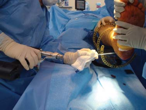 Figure 2.13. Applying skinny wire, utilizing a damp saline sponge to aid in guiding and cooling the wire. |
An easy technique for application of external fixation for the foot and ankle involves applying a calcaneal transosseous wire as the initial wire. This is termed “reference wire” and helps the surgeon set the proximal–distal position of the external fixator. The external fixator is then held in position, orthogonal to the foot and leg. More axial wires are then placed on each ring of the tibial ring block. This sets the position of the external fixator along the long axis of the leg. However, because the wires are parallel, it can still be translated medially and laterally along the wires (Figure 2.15). Adjustment, anterior and posterior along the holes of the circular rings, can still be performed until the surgeon is satisfied with the appropriate position. These wires are then attached to the external fixator. At this point, the circular external fixator then becomes “locked” by placing the remaining wires. Once these wires are placed, there are wires at varying angles and the circular external fixator gains stability and will no longer shift. The remaining wires are placed as previously mentioned depending on anatomic location. Half-pins can then be substituted to obtain appropriate 90-degree angulation of the wires if so desired. They can also be utilized to just gain more stability similar to the drop wire mentioned earlier. The half-pins can either be placed through the anterior cortex of the tibia or the medial face of the tibia.
Stay updated, free articles. Join our Telegram channel

Full access? Get Clinical Tree


