Proximal Humeral Arthroplasty for Acute Fractures
Todd C. Moen
Louis U. Bigliani
INDICATIONS/CONTRAINDICATIONS
There are multiple options for the surgical treatment of fractures of the proximal humerus (Fig. 31-1) and the proper treatment for specific injuries remain controversial. Hemiarthroplasty is a useful surgical technique for treatment of certain fracture patterns of the proximal humerus. The typical indications for hemiarthroplasty are (a) four-part fractures and fracture dislocations, (b) head-splitting fractures, (c) impression fractures involving greater that 40% of the articular surface, and (d) selected three-part fractures in elderly patients with osteoporotic bone (1). Because alternative techniques such as closed reduction-percutaneous pinning, open reduction-internal fixation, head excision, and arthrodesis have yielded unsatisfactory results, hemiarthroplasty is the preferred treatment (2, 3, 4, 5, 6, 7, 8). Moreover, there may be some clinical scenarios in which primary reverse shoulder arthroplasty may also be considered, such as fractures in which the greater tuberosity is so comminuted or of such poor quality that healing around a prosthetic humeral arthroplasty is unlikely. In addition, any of the above fractures in the setting of concomitant rotator cuff insufficiency are frequently better treated with a primary reverse arthroplasty.
Contraindications for hemiarthroplasty for fractures of the proximal humerus include active soft-tissue infection, chronic osteomyelitis, and paralysis of the rotator cuff musculature. However, deltoid dysfunction is not a contraindication to hemiarthroplasty; adequate yet suboptimal function can be achieved in such a shoulder.
PREOPERATIVE PLANNING
As with the treatment of any patient, the first step is a detailed history and physical examination. From a patient’s history, it is important to elucidate the acuity of the injury, as well as if the patient has suffered a seizure or loss of consciousness. A comprehensive physical examination can be challenging to obtain, as the patient is likely in pain and the shoulder is affected by swelling from the injury. Nevertheless, it is critical to accurately assess the patient’s neurovascular status, paying particular attention to the axillary nerve and artery. Injuries to the axillary artery are considered limb-threatening and should be emergently evaluated with a vascular surgery consultation and advanced vascular imaging. Injuries to the brachial plexus and peripheral nerves occur not infrequently and can often be overlooked. Most of these injuries can be treated conservatively, as most are neurapraxias, and will spontaneously resolve over time, allowing for sufficient function. Given this typical benign course, these nerve injuries should not delay definitive management of the fracture. If a neurologic deficit persists, electromyographic analysis should be planned for 3 to 4 weeks after the injury to determine the extent of injury. If there is no improvement in neurologic status after 3 months, further evaluation should be considered. Operative exploration with neurolysis and/or grafting may be beneficial and should be performed in the first 3 to 6 months following the injury.
Appropriate radiographic studies are vital for completely delineating and understanding the fracture pattern. In most cases, a standard shoulder trauma series is sufficient to characterize the fracture. The standard shoulder trauma series includes (a) a true anteroposterior (AP) view of the scapula, (b) a transscapular lateral Y view,
and (c) an axillary lateral view (Fig. 31-2). The true AP view of the scapula is obtained by the x-ray beam angled 30 to 40 degrees obliquely to the coronal plane of the body. The axillary view is obtained by abducting the arm 20 to 30 degrees, with the tube directed into the axilla and the radiographic plate oriented above the shoulder; the arm does not need to be fully abducted. Often, the surgeon must position the arm, as the patient is unable due to pain. Alternatively, a Velpeau axillary view can be obtained. This is done by allowing the patient to have the affected arm in a sling for comfort and then lean backward over a radiographic plate, with the tube positioned over the patient, directed downward. If plain radiographs leave questions as to the fracture pattern, a computed tomography scan with 3-D reconstructions can be obtained. Finally, plain x-rays or a scanogram of the uninvolved arm can be obtained to aid in preoperative planning and prosthetic sizing, templating, and tensioning intraoperatively.
and (c) an axillary lateral view (Fig. 31-2). The true AP view of the scapula is obtained by the x-ray beam angled 30 to 40 degrees obliquely to the coronal plane of the body. The axillary view is obtained by abducting the arm 20 to 30 degrees, with the tube directed into the axilla and the radiographic plate oriented above the shoulder; the arm does not need to be fully abducted. Often, the surgeon must position the arm, as the patient is unable due to pain. Alternatively, a Velpeau axillary view can be obtained. This is done by allowing the patient to have the affected arm in a sling for comfort and then lean backward over a radiographic plate, with the tube positioned over the patient, directed downward. If plain radiographs leave questions as to the fracture pattern, a computed tomography scan with 3-D reconstructions can be obtained. Finally, plain x-rays or a scanogram of the uninvolved arm can be obtained to aid in preoperative planning and prosthetic sizing, templating, and tensioning intraoperatively.
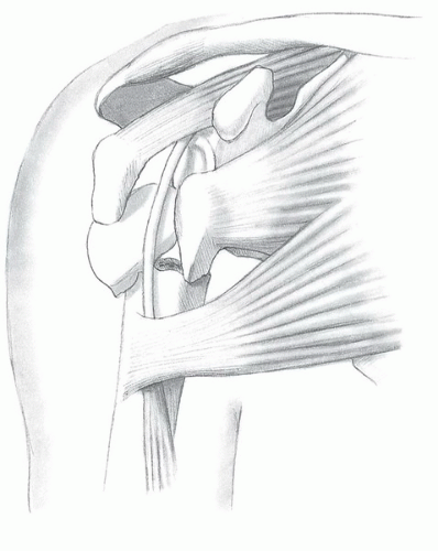 FIGURE 31-1 A four-part fracture of the proximal humerus. The humeral head is free-floating and displaced from both tuberosities and the shaft. The lesser tuberosity fragment is pulled medially by the subscapularis, the greater tuberosity fragment is pulled posteriorly and superiorly by the supraspinatus and infraspinatus, and the shaft fragment is pulled medially by the pectoralis major. |
SURGERY
Patient Positioning
As with all surgical procedures, proper patient positioning is the first step, and its importance in achieving a successful result cannot be overemphasized. The goal in positioning a patient for a hemiarthroplasty is to have global access to the shoulder. This access is facilitated by the use of an operating table with a cutaway section about the shoulder to allow more complete access posteriorly and a small moveable arm board on the operative side of the table; this allows for optimum positioning of the limb during the operation. The patient is initially positioned supine on the table, such that the greater trochanters of the hip are aligned with the break in the operating table. Two small towels are placed under the medial border of the scapula to negate any retraction. The head is secured in a positioner with the cervical spine aligned in neutral rotation and flexion. The operating table is then aligned in a modified beach-chair position. The table is first flexed at the hips and the foot of the bed is lowered to flex the knees. The back of the operating table is elevated so that the patient sits up at an angle of approximately 45 to 50 degrees (Fig. 31-3). The entire arm is prepped in a sterile fashion and draped such that the operative field extends to the medial clavicle, base of the neck, and under the axilla so that the arm can be freely moved throughout surgery. Care should be taken during surgical prep and scrubbing of the arm, as sharp medial fracture fragments may pose a hazard to adjacent vessels.
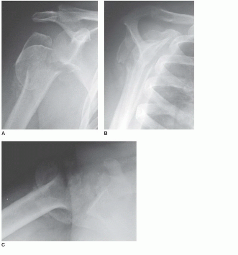 FIGURE 31-2 A: AP radiograph of a four-part fracture. B: Lateral view in the scapular plane. C: Axillary lateral view. |
Approach
A long deltopectoral approach is used. Start the incision just inferior to the clavicle, and just lateral of the coracoid process, extending lateral toward the deltoid insertion on the humeral shaft. Place large Gelpi retractors inferior and superiorly in the wound to facilitate exposure (Fig. 31-4). Continue dissection and identify the cephalic vein in the deltopectoral interval. Mobilize the cephalic vein, and retract the vein laterally. There are fewer tributary veins to the cephalic medially than laterally; therefore, lateral retraction can minimize bleeding. Nevertheless, there is typically a large transverse branch in the superior aspect of the deltopectoral interval. Care should be taken in the superior portion of the dissection to identify this branch and cauterize it. To facilitate exposure, the proximal third of the pectoralis insertion is detached and tagged with suture for later reattachment (Fig. 31-5). Rarely is the deltoid insertion on the clavicle and acromion removed; all attempts should be made to preserve this origin.
To begin the deep dissection, identify the coracoid process. The coracoid is the lighthouse to the shoulder. Dissection should not stray medial to this structure, given the risk of iatrogenic neurovascular injury (Fig. 31-6). Place a broad retractor underneath the lateral border of the coracoid muscles, avoiding vigorous retraction; this retractor provides an additional barrier of safety to the medial neurovascular structures. If necessary, a small portion of the leading edge of the coracoacromial ligament can be resected to facilitate proximal exposure; however, a bulk of this ligament must remain to preserve superior stability. Place another broad retractor under the deltoid, retracting this muscle laterally. Identify the long head of the biceps brachii (LHB) distally, and follow it proximally (Fig. 31-7). The LHB is the key landmark at this point of the procedure, as it leads to the glenoid and center of the shoulder, and can help to orient in identification of individual fracture fragments.
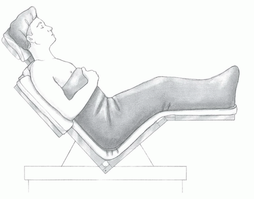 FIGURE 31-3 Place the patient in a modified beachchair position with the back flexed approximately 30 to 40 degrees and the lateral border of the scapula and thorax at the edge of the table. |
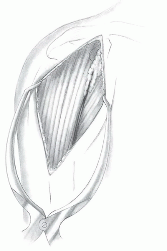 FIGURE 31-4 Use a long deltopectoral approach starting just below the clavicle and extending over the lateral aspect of the coracoid to the deltoid insertion on the humeral shaft. |
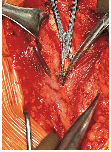 FIGURE 31-5 We typically detach the superior insertion of the pectoralis major to improve the exposure. |
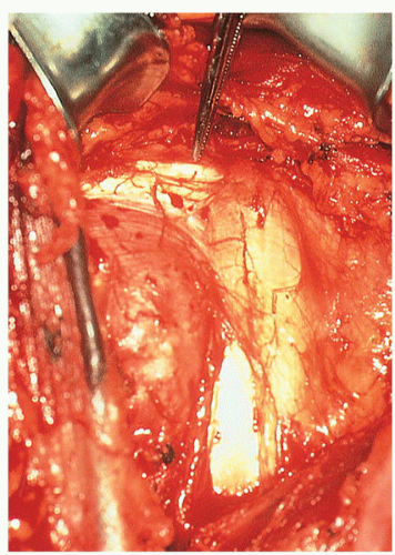 FIGURE 31-6 Carefully identify the coracoid process, coracoacromial ligament, and conjoined tendon. Define the lateral border of the strap musculature. We often resect the leading edge of the coracoacromial ligament to maximize the proximal exposure. Take care to avoid dissection medial to the strap muscles, as the neurovascular structures are within close proximity. |
Exposure of the Fracture
At this point in the procedure, the fracture fragments must be identified and mobilized, and the LHB serves as a landmark to the individual parts. Typically, the lesser tuberosity lies medial to the LHB and the greater tuberosity lateral, with the head—in varying degrees of comminution—lying between the tuberosities. With the individual fragments identified, each tuberosity is tagged with a no. 2 nonabsorbable suture. Use swedged-on needles and place them into the tendon proximal to the tuberosity insertion. The suture is placed in cuff tendon, proximal to the tuberosity insertion, thereby avoiding further iatrogenic comminution to the fragment. Each tuberosity is mobilized sufficiently medially, laterally, superiorly, and inferiorly. Tag the LHB with a nylon suture and protect it. With the tuberosities and LHB tagged and mobilized, attention is turned to the removal of the humeral head (Fig. 31-8). Removal of the head should be done carefully, without undue force. To accomplish this, follow the fracture line that typically lies in the bicipital groove to the rotator interval, and make a release in the rotator interval. Release only what is necessary to remove the head in an attempt to preserve as much soft-tissue attachments to the tuberosities as possible. Preserve any loose fragments of the cancellous bone as well as the humeral head for use as autogenous bone graft.
Two situations that can arise at this point in the case must be addressed with caution. First of all, if treatment has been delayed beyond 7 to 10 days after the initial injury, particular care must be taken in mobilizing the tuberosities and removing the humeral head. Scarring and adhesions make these tasks considerably more difficult. Secondly, if the head is dislocated anteriorly below the coracoid and medial to the strap muscles, caution must be exercised given the proximity of neurovascular structures and potential for neurovascular injury. Anticipation and recognition of the potential for vascular injury are important. If preoperative radiographs demonstrate an anterior dislocation of the head associated with fracture, advanced imaging studies such as angiography or MRA should be considered to identify the relationship between humeral head and vessels.
The presence or availability of a surgeon skilled in vascular repair may be invaluable should injury occur during the removal of humeral head from its medially dislocated position.
The presence or availability of a surgeon skilled in vascular repair may be invaluable should injury occur during the removal of humeral head from its medially dislocated position.
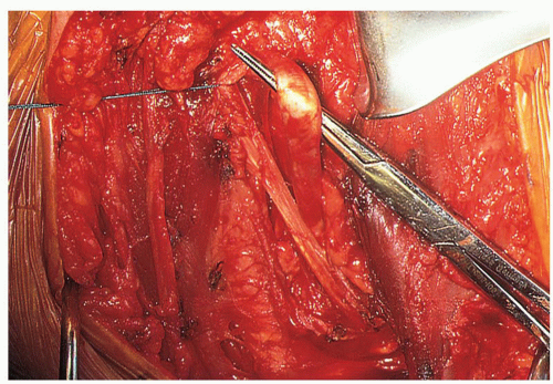 FIGURE 31-7 Identify the distal portion of the LHB and follow it proximally. This will help differentiate between the lesser and greater tuberosities and define the rotator interval. |
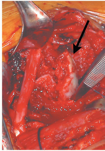 FIGURE 31-8 The humeral head (arrow) is usually a free-floating fragment that can be removed using a metal finger. |
In rare instances where the head has been dislocated laterally, it may be possible to remove the head and place the prosthesis without disturbing the rotator interval or soft-tissue attachment between the tuberosities. In this situation, leave the greater and lesser tuberosities together and elevate them as a unit, or “hood.” Generally, however, the interval must be opened in the area of the bicipital groove to allow atraumatic removal of the head. In either case, preserve any loose fragments or cancellous bone, including the humeral head, and save them as autogenous graft.
At this point in the procedure, we evaluate the subacromial space, external impingement, and rotator cuff pathology. If there is a large subacromial spur in the CA ligament, or if the patient has an impingement configuration of the acromion, it can be worthwhile to perform an anterior acromioplasty, although this is not a routine part of the procedure. If an acromioplasty is performed, the bony resection is conservative, and the CA ligament is preserved and repaired to the medial acromion with nonabsorbable sutures. Finally, evaluate for a tear in the rotator cuff; if present, it should be repaired. However, the rotator cuff is generally intact in this group of patients, unless there is preexisting cuff disease.
Shaft Preparation and Prosthesis Placement
The shaft of the humerus must be prepared in a very gentle manner, as the bone typically is osteoporotic, and there may be a nondisplaced fracture of the shaft. If there is a fracture of the shaft, fixation should be performed prior to implantation of the prosthesis. This can be accomplished with cerclage wires, cables, or heavy nonabsorbable sutures. The combination of the wires or sutures with cementation of the prosthesis usually provides a stable reconstruction. The humerus is exposed for canal preparation by extending and externally rotating the arm. Lifting the elbow in a distal-to-proximal direction will deliver the shaft into the wound. Place medial and lateral Darrach retractors posterior to the shaft for full exposure. Next, open and prepare the medullary canal with sequential reamers (Fig. 31-9).
It is vitally important to determine the proper size and position of the prosthesis. This involves three aspects: retroversion, height, and head size. The current generation of modular prosthetic shoulder implants greatly increases the ability to recreate proximal humeral anatomy. In addition, improved instrumentation allows reproducible version assessment and the ability to trial numerous head sizes and offsets that will maximize motion, stability, and tuberosity repair.
Version is assessed with the use of an intramedullary alignment system equipped with an outrigger that references the forearm (Fig. 31-10). Normal proximal humeral anatomy is variable, but we generally position the implant in approximately 25 to 30 degrees of retroversion. The only exception to this guideline is in the case of a chronic posterior fracture dislocation, in which we would choose less retroversion. Other techniques to assess version include positioning of the fins of the prosthesis relative to the distal aspect of the bicipital groove, and palpating and referencing off of the epicondylar axis of the elbow (Fig. 31-11); however, some modern designs do not have fins. The final version should be determined after the trial implant has been placed and the prosthesis reduced. This decision-making process involving version is discussed below.
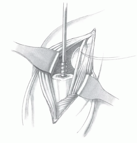 FIGURE 31-9 Prepare the medullary canal with sequential handheld reamers prior to cement fixation. |
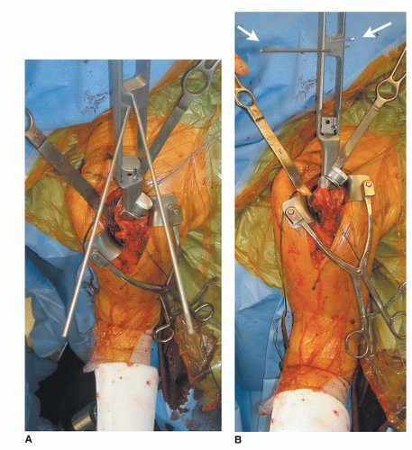 FIGURE 31-10 A,B: The use of an instrumentation system with an outrigger (arrows) that references the forearm is helpful in assessing retroversion of the component. With the arm in neutral rotation, the humeral head should face the glenoid. |
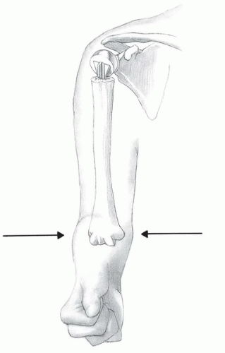 FIGURE 31-11 Alternatively, palpate the distal humeral epicondyles with the thumb and forefinger. Depending on the implant being used, the fins of the prosthesis can be oriented with reference to the bicipital groove. In fractures, the distal portion of the groove may still be visualized. |
Next, assess the height of the prosthesis and size of the head. Use a trial stem with an interference fit to assist in maintaining the elevated position of the component when trial reduction is performed. Alternatively, place a sponge in the canal to keep the component elevated (Fig. 31-12). Some implant systems have devices to assist with height positioning. Seat the trial stem within the canal. Do not seat the collar of the prosthesis so deeply that it is placed against the remaining proximal shaft, because this will usually decrease the length
of the humerus and shorten the myofascial sleeve compromising the mechanical advantage of the deltoid and may lead to prosthetic instability. In general, elevate the collar above the proximal shaft to a position that will allow space for both the greater and the lesser tuberosities to be placed below the level of the head. When the greater tuberosity is reduced, its proximal portion should clear the head and overlap the proximal shaft by only a few millimeters.
of the humerus and shorten the myofascial sleeve compromising the mechanical advantage of the deltoid and may lead to prosthetic instability. In general, elevate the collar above the proximal shaft to a position that will allow space for both the greater and the lesser tuberosities to be placed below the level of the head. When the greater tuberosity is reduced, its proximal portion should clear the head and overlap the proximal shaft by only a few millimeters.
Related posts:
 Arthroscopic Repair of Posterior Instability
 Arthroscopic Repair of SLAP Lesions
 Open Repair of Anterior Shoulder Dislocations and Subluxations
 Mini-open and Open Techniques for Full-Thickness Rotator Cuff Repairs
 Operative Treatment of Displaced Surgical Neck Fractures of the Proximal Humerus
 Total Shoulder Replacement: Managing Soft-tissue Deficiencies
Stay updated, free articles. Join our Telegram channel

Full access? Get Clinical Tree


