Pictorial Guide to Nerve Conduction Techniques


Pictorial Guide to Nerve Conduction Techniques


Henry L. Lew

Su-Ju Tsai


Abbreviations for the electrode placement are as follows:


E1 Placement of the active electrode
E2 Placement of the reference electrode
G Placement of the ground electrode
S • Cathode Placement of the cathode for stimulation
  • Anode Relation of stimulator anode to the cathode


Cranial Nerves


Table 9-1 Cranial Nerve VII to Nasalis (Fig. 9-1)


image
Figure 9-1 • Cranial nerve VII
Electrode placement
E1 Over nasalis (lateral side of midnose)
E2 Over contralateral nasalis
G On the cheek or chin
S Postauricular stimulation—behind the lower ear, below the mastoid process and behind the neck of the mandible
Normal values
  Mean ± SD Normal limit
Onset latency (1) 3.5 ± 0.4 ms ≤4.2 ms
Amplitude (2)   ≥1 mV
Note: Alternate recording sites from other facial muscles as needed to evaluate specific branches of CN VII.


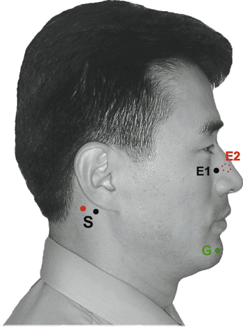
Table 9-2 Blink Reflex (Fig. 9-2)


image
Figure 9-2 • Blink reflex
Electrode placement
E1 Over bilateral orbicularis oculi muscle, lower lateral portion
E2 Medial inferior orbit
G Chin
S Cathode At the supraorbital notch
Anode Superiorly
Normal values (3) (n = 83)
  Mean ± SD (Normal limit) Side-to-side difference (Normal limit)
R1 latency 10.5 ± 0.8 ms (≤13.0 ms) 0.3 ± 0.9 ms (≤1.2 ms)
Ipsilateral R2 latency 30.5 ± 3.4 ms (≤41.0 ms) 1.0 ± 3.4 ms (≤4.4 ms)
Contralateral R2 latency 30.5 ± 4.4 ms (≤44.0 ms)  
Note: Amplitudes are variable.


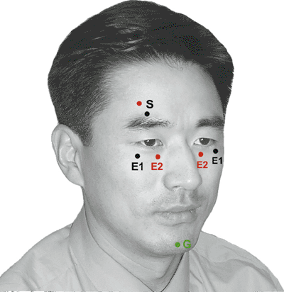
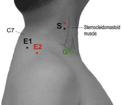
Table 9-3 Cranial Nerve XI to Trapezius (Fig. 9-3)


image
Figure 9-3 • Cranial nerve XI
Electrode placement
E1 Over the upper trapezius, midway between C7 spinous process and acromion.
E2 On acromion
G Medial clavicle
S Cathode At the posterior edge of the sternocleidomastoid muscle
Anode Superiorly
Normal values (4,5) (n = 30)
  Mean ± SD Normal limit
Onset latency 2.2 ± 0.4 ms ≤ 3.0 ms
Peak amplitude 3.9 ± 1.6 mV ≥ 1.0 mV


Upper Body


Upper Body: Motor Nerves


Table 9-4 Phrenic Nerve (Fig. 9-4)


image
Figure 9-4 • Phrenic nerve
Electrode placement
E1 On the xiphoid process
E2 On the costal margin, at anterior axillary line
G Medial sternum
S Cathode 3 cm above the clavicle, along the posterior border of the sternocleidomastoid muscle
Anode Superiorly
Normal values (6) (n = 50)
  Mean ± SD Normal limit
Onset latency 6.3 ± 0.8 ms ≤8.6 ms
Amplitude 597 ± 139 μV ≥400 μV


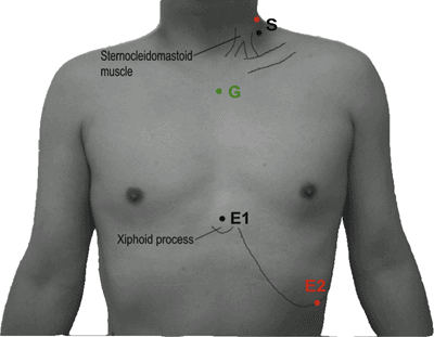
Table 9-5A Long Thoracic Nerve-1 to Serratus Anterior (Fig. 9-5A)


image
Figure 9-5 • A. Long thoracic nerve
Electrode placement (7) (Fig. 9-5A)
E1 Self-adhesive, 8.0 × 0.5-cm, ring-type electrode—cranial end at nipple level (5 cm distal to the bipolar stimulator) in line with the bipolar stimulator contact points and the anterior superior iliac spine
E2 Self-adhesive surface electrode over the seventh rib distal to the pectoralis muscle
G Over the ipsilateral latissimus dorsi
S In the axilla just anterior to the midaxillary line
Normal values (7) (n = 15, self-adhesive ring-type electrode recording)
  Side Mean ± SD Normal limit
Onset latency Right 2.3 ± 0.5 ms ≤3.5 ms
Left 2.3 ± 0.4 ms ≤3.2 ms
Side-to-side difference 0.3 ± 0.2 ms ≤0.6 ms
Amplitude Right 3.8 ± 1.9 mV ≥1.6 mV
Left 3.9 ± 1.9 mV ≥1.2 mV
Side-to-side difference 0.6 ± 0.6 mV ≤2 mV


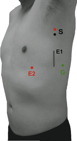
Table 9-5B Long Thoracic Nerve-2 to Serratus Anterior (Fig. 9-5B)


image
Figure 9-5 • B. Long thoracic nerve
Electrode placement
E1 A needle electrode is placed into the digitation of the serratus anterior muscle over the fifth rib, along the midaxillary line.
E2 Two cm distal to the E1 (no need if a concentric needle electrode is used for E1)
G Over the 12th rib level at the anterior axillary line
S Cathode Slightly above the upper margin of the clavicle lateral to the clavicular head of the sternocleidomastoid muscle
Anode Superomedially
Normal values (8) (n = 16, concentric needle recording)
Age (years) Onset latency Mean ± SD Normal limit
20–35 3.6 ± 0.3 ms ≤4.2 ms
36–50 3.8 ± 0.4 ms ≤4.4 ms
51–65 4.0 ± 0.4 ms ≤4.8 ms


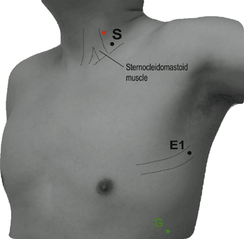
Table 9-6 Axillary Nerve to Deltoid (Fig. 9-6)


image
Figure 9-6 • Axillary nerve
Electrode placement
E1 Midway between acromion and deltoid tubercle
E2 At deltoid tubercle
G Between the stimulating point and active electrode
S Cathode Supraclavicular fossa
Anode Superomedially
Normal values (9) (n = 62)
  Mean ± SD Normal limit
Onset latency 3.9 ± 0.5 ms ≤5.0 ms
Note: No information on amplitude is available (9).


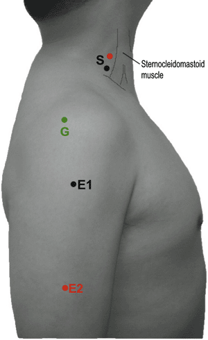
Table 9-7 Musculocutaneous Nerve to Biceps (Fig. 9-7)


image
Figure 9-7 • Musculocutaneous nerve
Electrode placement
E1 Midpoint of the biceps brachii muscle belly
E2 Distal biceps tendon
G Over the acromion
S Cathode Supraclavicular fossa
Anode Superomedially
Normal values (9) (n = 62)
  Mean ± SD Normal limit
Onset latency 4.5 ± 0.6 ms ≤5.7 ms
Note: No information on amplitude is available (9).


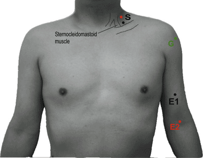
Table 9-8 Suprascapular Nerve (Fig. 9-8)


image
Figure 9-8 • Suprascapular nerve
Electrode placement
E1 A concentric recording needle (E2 = reference/outer cannular of needle) Supraspinatus: Insert the needle just above the scapular spine at the midpoint. Advance the needle in a downward and forward direction until the needle touches the scapula, then withdraw it 2–3 mm. Infraspinatus: Insert the needle 3 cm below the scapular spine and 3 cm lateral to the medial border of the scapula.
G Over the posterolateral shoulder
S Cathode Supraclavicular fossa
Anode Superomedially
Normal values (9) (n = 62)
Onset latency Mean ± SD Normal limit
Supraspinatus recording 2.7 ± 0.5 ms ≤3.7 ms
Infraspinatus recording 3.3 ± 0.5 ms ≤4.2 ms
Note: No information on amplitude is available (9).


Table 9-9 Thoracodorsal Nerve to Latissimus Dorsi (Fig. 9-9)


image
Figure 9-9 • Thoracodorsal nerve
Electrode placement (10)
E1 Supine position with the arm abducted to 90 degrees. E1 is on the posterior axillary line at the intersection of the line horizontally drawn from the inferior angle of the scapula.
E2 On the posterior axillary line distal to E1
G On the chest wall, between E1 and S1
S1 Cathode In the axilla toward the lateral margin of the scapula
Anode Superior
S2 Cathode Erb’s point
Anode Superior
Normal values (10) (n = 30)
    Mean ± SD Range
Axilla (S1) Onset latency 1.9 ± 0.4 ms ≤2.7 ms
Amplitude, right 4.1 ± 1.8 mV ≥1.4 mV
Erb’s point (S2) Onset latency 3.6 ± 0.4 ms ≤4.5 ms
Amplitude 6.0 ± 2.0 mV ≥2.0 mV


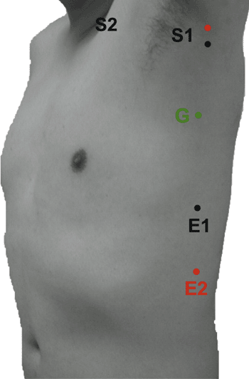
Table 9-10 Median Nerve to the Abductor Pollicis Brevis (Fig. 9-10)


image
Figure 9-10 • Median nerve to the abductor pollicis brevis
Electrode placement
E1 Midline between the first metacarpophalangeal joint and the first carpometacarpal joint
E2 Distal to E1 on the first metacarpophalangeal joint
G On the dorsum of the hand
S Cathode S1: 8 cm proximal to the E1, measured first to the midpoint of the distal wrist crease and then on the line between the tendons of the flexor carpi radialis and the palmaris longus
S2: On the antecubital crease, at the medial border of the biceps brachii tendon
Anode Proximal
Normal values (11,12) (n = 47)
  Mean ± SD Normal limit
Onset latency 3.7 ± 0.3 ms ≤4.3 ms
Amplitude 13.2 ± 5.0 mV ≥5.0 mV
Nerve conduction velocity 56.7 ± 3.8 m/s ≥50 m/s
Normal values (13) (n = 243)
  Mean ± SD Normal limit
Onset latency 3.7 ± 0.5 ms ≤4.7 ms
Amplitude 10.2 ± 3.6 mV ≥3.0 mV
Nerve conduction velocity 57 ± 5 m/s ≥47 m/s


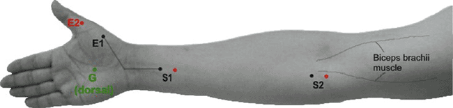
Table 9-11 Median Nerve (Anterior Interosseous Branch) to the Pronator Quadratus (Fig. 9-11)


image
Figure 9-11 • Median nerve (anterior interosseous branch) to the pronator quadratus
Electrode placement
E1 Centrally over the dorsum of the forearm, 3 cm proximal to the ulnar styloid
E2 On the medial dorsum of the wrist over the ulnar styloid process
G On the dorsal forearm, between the E1 and stimulating electrodes
S Cathode On the antecubital crease, at the medial border of the biceps brachii tendon
Anode Proximally
Normal values (14) (n = 52)
  Right Left
Onset latency 3.6 ± 0.4 ms 3.5 ± 0.4 ms
Onset to peak amplitude 3.1 ± 0.8 mV 3.1 ± 0.8 mV


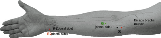
Table 9-12 Radial Nerve to the Extensor Digitorum (Fig. 9-12)


image
Figure 9-12 • Radial nerve to the extensor digitorum
Electrode placement
E1 Proximal third from the antecubital crease (S1), over the belly of the extensor digitorum
E2 On the medial dorsum of the wrist over the ulnar styloid process
G Between the E1 and the S1
S Cathode S1: In the antecubital fossa just lateral to the biceps tendon as the tendon crosses the flexor crease
S2: In the axilla between the coracobrachialis and the long head of the triceps
Anode Proximally
Normal values (15) (n = 30)
  Mean ± SD Normal limit
Onset latency 2.6 ± 0.4 ms ≤3.5 ms
Amplitude 11.2 ± 3.5 mV ≥4.3 mV
Conduction velocity 68 ± 7.0 m/s ≥54 m/s


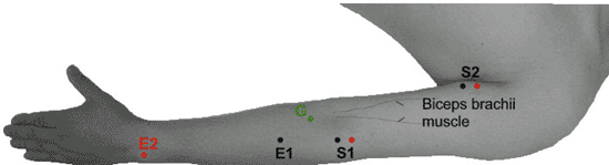
Table 9-13 Radial Nerve to the Extensor Indicis Proprius (Fig. 9-13)


image
Figure 9-13 • Radial nerve—to the extensor indicis proprius
Electrode placement (16)
E1 Concentric needle electrode into the extensor indicis proprius, at the distal third of the dorsal forearm and on the dorsum of the ulna (E2 = outer cannula of needle)
G Between E1 and S1, on the dorsum of the forearm
S Cathode S1: In pronation of the forearm; 4 cm proximal to the needle insertion site, radial border of the extensor carpi ulnaris muscle
S2: In pronation of the forearm; 5 cm proximal to the lateral epicondyle, lateral border of the triceps brachii muscle
S3: Erb Point
Anode Proximally
Normal values (n = 49)
  Mean ± SD Normal limit
Distal latency (17) 2.4 ± 0.5 ms ≤2.9 ms
Conduction velocity (16)    
S1-S2 61.6 ± 5.9 m/s ≥50 m/s
S2-S3 72.0 ± 6.3 m/s ≥60 m/s


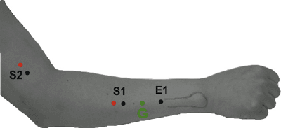
Table 9-14 Ulnar Nerve to the Abductor Digiti Minimi (ADM) (Fig. 9-14)


image
Figure 9-14 • Ulnar nerve—to the abductor digiti minimi
Electrode placement
E1 On the border of the palm and dorsum of the hand, halfway between the wrist crease and the base of the little finger
E2 Distal to the fifth metacarpophalangeal joint
G On the dorsum of the hand or between the stimulating and recording electrodes
S Cathode The arm is in a 45 degrees abducted and externally rotated position with the elbow moderately flexed to 90–135 degrees (18).
S1: 2 cm proximal to the E1, along the radial border of the tendon of the flexor carpi ulnaris
S2: 2 cm distal to the ulnar groove at the elbow
S3: 10 cm proximal to the S2, measured in a curve along the ulnar groove to a point between triceps and brachialis
S4: 10 cm proximal to S3 in the axilla
Anode Proximally
Normal values (n = 31)
  Mean ± SD Normal limit
Onset latency (18) 3.2 ± 0.5 ms ≤4.2 ms
Amplitude 6.14 ± 1.90 mV ≥2.3 mV
Nerve conduction velocity (18,19,20)    
S1-S2 61.8 ± 5.0 m/s ≥53 m/s
S2-S3 62.7 ± 5.5 m/s ≥52 m/s
S3-S4 62.8 ± 6.0 m/s ≥51 m/s
Normal values (21) (n = 248)
  Mean ± SD Normal limit
Distal latency (21) 3.0 ± 0.3 ms ≤3.6 ms
Amplitude, peak to peak (21) 11.6 ± 2.1 mV ≥7.4 mV
Conduction velocity (21)    
S1-S2 61 ± 5 m/s ≥51 m/s
S2-S3 61 ± 9 m/s ≥43 m/s
S3-S4 61 ± 7 m/s ≥47 m/s


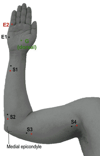
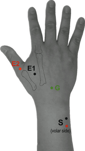
Table 9-15 Ulnar Nerve to the First Dorsal Interosseous (Fig. 9-15)


image
Figure 9-15 • Ulnar nerve—to the first dorsal interosseous
Electrode placement
E1 On the dorsum of the hand, the first web space, 1 cm radial to the midpoint of the second metacarpal bone
E2 Over the first metacarpophalangeal joint
G Between E1 and S1
S Cathode At the ulnar wrist crease, along the radial border of the tendon of the flexor carpi ulnaris
Anode Proximally


Normal values (22) (n = 373)
  Onset latency Amplitude
Age (years) Mean Limit Mean Limit
<20 3.3 ms ≤4.2 ms 15 mV ≥8 mV
20–29 3.4 ms ≤4.1 ms 14 mV ≥8 mV
30–39 3.3 ms ≤4.4 ms 15 mV ≥6 mV
40–49 3.2 ms ≤4.2 ms 13 mV ≥6 mV
50–59 3.4 ms ≤4.4 ms 13 mV ≥6 mV
60–69 3.6 ms ≤4.5 ms 12 mV ≥7 mV
>70 3.6 ms ≤4.2 ms 12 mV ≥8 mV
Note: No summarized values are available (22).
Mean side-to-side difference, FDI = 0.2 ms (0.0–1.3); ipsilateral difference, FDI – ADM = 0.9 ms (0.2–2.0) (22).

Only gold members can continue reading. Log In or Register to continue

Stay updated, free articles. Join our Telegram channel

Sep 7, 2016 | Posted by in PHYSICAL MEDICINE & REHABILITATION | Comments Off on Pictorial Guide to Nerve Conduction Techniques

Full access? Get Clinical Tree

Get Clinical Tree app for offline access