INTRODUCTION
Since the development of high-frequency transducers in the 1980s, physicians and ultrasonographers have been utilizing musculoskeletal ultrasound to provide detailed imaging of anatomic structures. Today, many practitioners are incorporating musculoskeletal ultrasound as a useful tool to help evaluate and treat their patients. As the popularity of musculoskeletal ultrasound continues to increase, a better understanding of its capabilities will be required.
This chapter surveys essential knowledge about musculoskeletal ultrasound, including the indications for its use; advantages and disadvantages of this technique over other imaging modalities; and the basic physics of ultrasound. The appearance of normal musculoskeletal tissues is reviewed and illustrated using numerous images of normal and pathologic structures evaluated through diagnostic musculoskeletal ultrasound examination.
INDICATIONS
After obtaining a detailed history and performing a comprehensive physical examination, the physician may determine that further diagnostic workup is required to identify the source of a patient’s dysfunction. A musculoskeletal ultrasound examination can provide high-resolution scans of various anatomic structures, including tendons, ligaments, nerves, joint capsules and muscles. Consequently ultrasound can be used to diagnose tendon pathology, muscle injury, ligament damage, and joint effusions. In addition, ultrasound can be utilized to evaluate other structures throughout the musculoskeletal system while helping to guide interventional procedures in real time.
ADVANTAGES
Currently a vast array of modalities is available that can provide imaging of the human body. Musculoskeletal ultrasound offers certain advantages over other forms of imaging such as radiography, computed tomography (CT), and magnetic resonance imaging (MRI).
Ultrasound can be used to provide real-time, high-resolution images that require no preparation aside from body positioning. Unlike MRI or CT, ultrasound can be utilized to provide a dynamic and interactive examination. Apart from its ability to provide static imaging, ultrasound allows the physician to investigate a patient’s dynamic complaints such as “snapping” or “popping,” which can be evaluated while performing provocative maneuvers.
In addition, in response to patient feedback, the ultrasound beam can be targeted over involved areas of tenderness, which may help correlate patient symptoms with abnormalities identified on the ultrasound scan. In comparison, MRI and CT may identify many abnormalities that have no clinical relevance to the patient’s symptoms. Furthermore, utilizing diagnostic musculoskeletal ultrasound, structures can be compared with the contralateral limb. Musculoskeletal ultrasound images of many soft tissues typically have greater resolution than those provided by MRI or CT.
Musculoskeletal ultrasound is also relatively safe and inexpensive to use on children, individuals with pacemakers, and pregnant women, since it emits no radiation and lacks a high-powered magnet. In addition, in comparison with CT, MRI, and radiography, ultrasound units can be portable, allowing utilization outside a hospital or radiology suite. Finally, because ultrasound can identify structures such as vessels and nerves, it can be used to safely and accurately guide musculoskeletal interventional procedures.
DISADVANTAGES
Although musculoskeletal ultrasound is a highly valuable diagnostic tool, it does have limitations. The quality of the ultrasound examination is ultimately dependent on the skill of the examiner. The high-resolution images obtained from ultrasound provide a limited field of view, which is not ideal for a larger area of study. Ultrasound does not penetrate through bone and cannot fully evaluate some intraarticular structures. The utility of diagnostic ultrasound in obese or very muscular individuals may be limited as tissue resolution is sacrificed at greater tissue depth.
ULTRASOUND BASICS
An ultrasound machine has three components: a transducer, the connecting cord, and the main apparatus. The transducer contains an array of thin crystals. An ultrasound wave is produced when an electric current is applied to the crystals, which causes them to vibrate, creating a sinusoidal sound wave. This transformation of electrical energy to mechanical energy is known as the piezoelectric effect. Because these waves are not propagated well through air, a medium, such as water or gel, is necessary to enable them to penetrate tissue. The sound wave then travels until it encounters a change in the stiffness or density of an adjacent tissue. This difference is known as an acoustic interface. The acoustic interface will reflect a portion of the sound wave, while allowing some of the wave to pass through. The reflected wave reaches the transducer and produces a two-dimensional (2D) image. The conversion of mechanical energy back to electrical energy is known as the reverse piezoelectric effect. The greater the number of waves reflected by the acoustic interface, the brighter the image appears on the screen, and the fewer the waves reflected by the acoustic interface, the darker the image appears on the screen.
SCANNING BASICS
As stated earlier, the images produced by the ultrasound machine provide a limited field of view. Images seen on the screen produce a 2D “slice” through the structure being examined. Therefore it is imperative that the examiner follow a protocol to ensure that the entire area is interrogated, examining all tissues in orthogonal planes. Musculoskeletal tissues are best described by their echotexture, which represents the internal echo pattern specific to certain tissues. The relative brightness or darkness of a structure imaged with ultrasound is referred to as echogenicity. An image is said to be hyperechoic if it is brighter compared with another image. If an image is darker than another image, it is said to be hypoechoic. If an image appears to be absent or devoid of any image, it is described as anechoic.
Ultrasound is also associated with various artifacts. Anisotropy, a common artifact, is created when an ultrasound beam does not hit a structure at 90 degrees. As stated earlier, the ultrasound wave will travel until it hits a structure, whereupon it will be reflected back to the transducer to produce an image. The greater the portion of the wave that is reflected or the greater the interface differential, the more echogenic will be the image produced. If the wave does not hit the structure perpendicularly, only a part of the wave will be reflected back to the transducer, changing a hyperechoic image to a hypoechoic image. This creates the artifact known as anisotropy. Anisotropy occurs more commonly in tendons. To avoid anisotropy, the examiner must be careful to ensure that the transducer is oriented at 90 degrees to the targeted tissue.
There is an inverse relationship between ultrasound frequency and penetration depth. Typically, linear array high-frequency transducers produce an image with better resolution at the cost of decreased depth penetration. However, evaluation of deeper tissues may necessitate the use of a low-frequency curvilinear transducer, which provides greater depth of penetration but at the cost of lower resolution. The depth of the ultrasound image can be adjusted using the settings on the ultrasound unit. By increasing the depth, structures that lie deeper can be brought into an appropriate field of view. Equivalent to adjusting the focus on a camera, the structure being examined should be placed within the focal zone in order to enhance tissue resolution. Gain relates to the overall brightness seen on the ultrasound screen and can be increased or decreased based on subjective appearance. Time gain compensation (TGC) is similar, although the gain at various tissue depths can be adjusted appropriately. Many ultrasound machines have predefined settings for specific body parts being examined.
NORMAL TISSUES
Distinguishing structures seen on ultrasound can be a difficult task for novice ultrasonographers; however, most musculoskeletal tissues have a characteristic echogenic pattern when viewed in orthogonal planes. As stated earlier, it is important to describe structures seen on ultrasound in terms of echogenicity, echotexture, susceptibility to anisotropy, compressibility, and presence or absence of blood flow. The normal appearance of several soft tissues is described below and summarized in Table 39–1.
| Structure | Echogenicity | Transverse Appearance | Longitudinal Appearance | Susceptibility to Anisotropy | Compressible | Doppler Flow |
|---|---|---|---|---|---|---|
| Tendons | Hyperechoic | “Broom end” | Fibrillar | High | No | Negative |
| Ligaments | Hyperechoic | “Broom end” | Fibrillar | High | No | Negative |
| Nerves | Mixed | “Honeycomb” | Fascicular | Mild | No | Negative |
| Muscles | Mixed | “Starry night” | Feathery | Mild | Yes | Negative |
| Vessels | Anechoic | N/A | N/A | N/A | Yes | Positive |
| Bone | Hyperechoic | Linear, smooth | Linear, smooth | — | No | Negative |
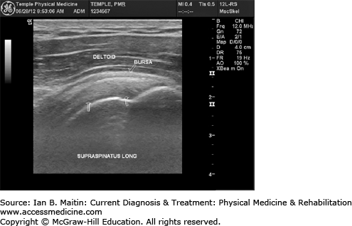
Tendons exhibit a fibrillar pattern when imaged longitudinally and a “broom end” pattern when imaged transversely. As these tissues are typically hyperechoic and highly susceptible to anisotropy, it is important to focus the ultrasound waves perpendicularly when imaging tendons. Tendons are not compressible and do not normally have any blood flow seen on Doppler examination. Longitudinal and transverse views of various tendons are shown in Figures 39–1,Figures 39–2,Figures 39–3,Figures 39–4,Figures 39–5,Figures 39–6,Figures 39–7,Figures 39–8,Figures 39–9,Figures 39–10,Figures 39–11,Figures 39–12,Figures 39–13,Figures 39–14,Figures 39–15,Figures 39–16,Figures 39–17, and 39–18.
Related posts:


Stay updated, free articles. Join our Telegram channel

Full access? Get Clinical Tree


