Minimally Invasive Hip Fracture
Yoram A. Weil
Rami Mosheiff
BACKGROUND
Hip fracture has become a modern epidemic. The incidence of hip fractures is increasing throughout the world, as is the cost of treatment.1 Despite the existing surgical treatment, the mortality from hip fracture is still high, and reported to be about 15% to 20% in the first year post fracture. In older patients with severe comorbidities the mortality is tripled due to the fracture.2
Optimally, minimally invasive procedures are performed on these often frail patients. The goals of such surgery should include minimal blood loss, efficient and reliable procedures, and adequate stability allowing immediate postoperative mobilization.
As numerous types of implants and techniques are available, this chapter will discuss three types of modern, minimally invasive techniques, all well supported in the orthopaedic literature. This includes navigated-assisted percutaneous screw fixation for femoral neck fractures, percutaneous compression plating for stable intertrochanteric fractures, and intramedullary nailing for unstable pertrochanteric fractures. Arthroplasty for displaced femoral neck fractures is beyond the scope of this chapter.
NAVIGATED PERCUTANEOUS SCREW FIXATION FOR FEMORAL NECK FRACTURES
Nondisplaced fractures and displaced fractures in young patients are best treated with closed or open reduction and internal fixation, most commonly with cannulated cancellous screws.3 The rationale for using this fixation technique is to enable healing by controlled fracture impaction across parallel placed screws, allowing early weight-bearing and mobilization.
Although placement of screws is often trivialized, most surgeons tend to underestimate the technical requirements for accuracy of screw placement in terms of drill attempts, fluoroscopic time, and desired implant placement. Computerized navigation allows better accuracy for screw placement in terms of parallelism and screw spread within the femoral neck.4 Evidence shows that this leads to less mechanical complications.5
Fluoroscopic navigation is a modality that enhances the capacity of the intraoperative, conventional 2D fluoroscopy by displaying multiple orthogonal views simultaneously (such as anteroposterior and lateral) without actually performing live fluoroscopy.6,7 The advantages of this system are that trajectories of implants can be planned prior to their insertion, thus minimizing drilling attempts, reducing radiation, and decreasing operative time after setting up the system. A typical fluoroscopic navigation system comprises a computer, a tracking optical system, trackable surgical tools, and c-arm.
Optical trackers are attached to the patient’s bony anatomy (such as the iliac crest) and to the surgical tools and drill guides. Tracked fluoroscopic images are captured using either a calibration target on the c-arm or a mobile targeting device that should be displayed to the optical tracking device (“camera”) (Fig. 10.1). As the camera tracks the anatomical trackers and the c-arm tracker, the computer builds a coordinate system (x, y, z) on which the virtual image of the tracked instruments and their trajectories can be overlaid and displayed on all previously taken fluoroscopic images.
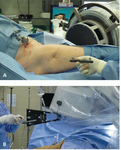 Figure 10.1 Setup for fluoroscopic navigation using optical tracking system. A: A tracker is mounted on the iliac crest and an optical calibration target is mounted on the c-arm fluoroscope. Alternatively, a mobile, handheld targeting device (X-spot) can be used instead (B) allowing more flexibility in image registration. |
INDICATIONS
Nondisplaced femoral neck fractures or displaced femoral neck fractures in young (<60 years) patients—after closed or open reduction.
PATIENT POSITIONING, PREPPING, AND DRAPING
The patient is positioned supine on a fracture table. The contralateral leg is placed in a well leg support or abducted, and the operative limb is draped free or a shower curtain is used based on surgeon preference. The ipsilateral iliac crest should be prepped as well for the placement of optical trackers.
FRACTURE REDUCTION
For nondisplaced fractures, gentle positioning without the use of excessive force is recommended. For displaced fractures several closed maneuvers are described. The Leadbetter maneuver consists of flexing the hip to 90 degrees, applying traction and internally rotating and then extending the hip with slight abduction. Traction, internal rotation, and extension can be performed using the fracture table. If satisfactory reduction cannot be achieved, especially on the lateral view (e.g., posterior sag of the femoral head is the usual deformity), open reduction should be then performed either through a separate Smith-Petersen approach8 or through an anterolateral extension of the Watson-Jones approach.9 The description of these approaches can be found elsewhere and is beyond the scope of this chapter. After satisfactory reduction, fixation can be inserted.
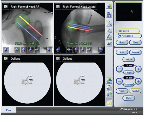 Figure 10.2 Screenshot of the navigation system at the time of intraoperative planning of screws’ trajectories. The “active” screw is designated in red (superior posterior one). A special feature in newer software version is “breakin” or “breakout” spheres allowing estimation of screw length before penetrating the joint. The sphere representing the borders of the femoral head is marked in green. |
FRACTURE FIXATION
The principle of fracture fixation is the creation of a stable construct consisting of three parallel cancellous screws in an inverted triangle formation—a proximal base consisting of an anterior and a posterior screw with an inferior screw supporting the femoral calcar and situated in the center of the femoral neck on the lateral view. It should be noted that the most distal starting point for the most distal screw should not be below the level of the lesser trochanter due to the risk of a subtrochanteric stress fracture, previously reported with these low starting points.10 Maximal parallelism and spread, especially in the lateral view should be achieved, in order to create as much stable construct as possible to avoid varus collapse and implant failure.5 The trajectory of the three screws can be planned on the computer screen prior to their actual insertion (Fig. 10.2). Then, sequential guidewire insertion, matching the plan, can be done using the navigation system.
The computerized navigation system allows virtual trajectory monitoring in all views while inserting the guidewires. One major drawback of this system is that long guidewires can bend during insertion, and since the computer cannot track the actual guidewire but only the trajectory of the drill guide, a few precautionary measures should be taken. First, a long navigated drill guide should be selected to create as straight a trajectory as possible. Second, tactile feedback during insertion is essential, and drill bit-tipped guidewires can improve tactile sensation. If any doubt exists, a verification fluoroscopy should be taken. Third, since the goal is to limit fluoroscopy to avoid radiation exposure, a simple measure of precalibrating guidewires’ length is performed—the guidewire is inserted through the drill guide, and the length of 75 to 80 mm of trajectory (the most common screw size for this procedure) is marked at the proximal part of the guidewire. This mark is copied to the rest of the guidewires.
The next step is actual navigation. The drill guide is placed over the patient’s skin until the trajectory of the inferior screw is appropriate while looking at the computer screen. A 3- to 4-cm incision is made proximal to this point and continued 0.5 cm distal to it. The skin, subcutaneous tissue, fascia, and vastus lateralis muscle are sharply dissected. At this point,
navigation can take place by meeting all of the planned trajectories in a serial fashion (Fig. 10.3). An assistant can place the guidewires while the surgeon navigates the drill guide to meet the planned trajectory. The guidewires are drilled to the previously marked area. Verification of AP and lateral fluoroscopic images are done after the insertion of all guidewires. Opening of the lateral cortex is done sequentially with a cannulated drill bit, and 6.5 or 7.3 mm partially threaded screws are inserted. As recent evidence shows that excessive femoral neck shortening can occur and can affect function,11,12 we prefer to insert long partial thread (32 to 40 mm) screws that cross the fracture, or one short thread screw to create intraoperative compression, and then to use two long-threaded or fully threaded screws to avoid further sliding (Fig. 10.4).
navigation can take place by meeting all of the planned trajectories in a serial fashion (Fig. 10.3). An assistant can place the guidewires while the surgeon navigates the drill guide to meet the planned trajectory. The guidewires are drilled to the previously marked area. Verification of AP and lateral fluoroscopic images are done after the insertion of all guidewires. Opening of the lateral cortex is done sequentially with a cannulated drill bit, and 6.5 or 7.3 mm partially threaded screws are inserted. As recent evidence shows that excessive femoral neck shortening can occur and can affect function,11,12 we prefer to insert long partial thread (32 to 40 mm) screws that cross the fracture, or one short thread screw to create intraoperative compression, and then to use two long-threaded or fully threaded screws to avoid further sliding (Fig. 10.4).
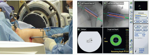 Figure 10.3 Navigating the guidewire to its desired position—the tracked drill guide is placed on the right entry point and the k-wire is drilled when the trajectory of the lowermost screw (active screw, in red) is met and the target and the depth gauge on the right hand part of the screen turns green. |
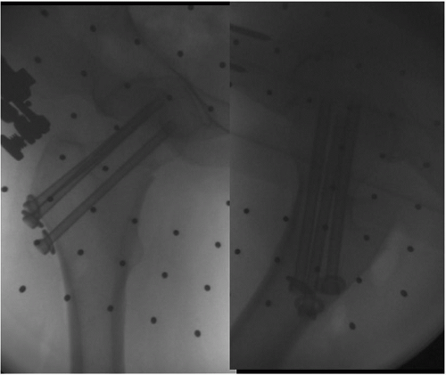 Figure 10.4 An intraoperative fluoroscopic image demonstrated the actual position of screws in both AP and lateral views. |
POSTOPERATIVE CARE
The wound is closed in layers: Fascia, subcutaneous tissue, and skin. In elderly patients, weight-bearing as tolerated is encouraged, with DVT prophylaxis for several weeks. In younger patients with unstable fractures, toe touch weight-bearing is commenced and progressed to weight-bearing as tolerated at 6 weeks postoperatively.
OUTCOME AND COMPLICATIONS
The incidence of complications in nondisplaced or valgus-impacted fractures is low. Screw protrusion into the femoral head can occur and screw implant removal is warranted in these cases. While infection is not common, it can be a devastating complication in elderly patients since arthroplasty after infected, failed fixation is not a viable option. Osteonecrosis and varus collapse are more common after displaced fractures and should be monitored. In cases of nonunion with a viable femoral head, a Pauwels type intertrochanteric osteotomy should be considered in young patients, while arthroplasty should be reserved for older, lowerdemand patients.
STABLE INTERTROCHANTERIC FRACTURES WITH PERCUTANEOUS SLIDING HIP SCREW DEVICE
Despite the popularity and success of nailing systems for intertrochanteric hip fractures, the sliding hip screw (SHS) is still considered the gold standard with less mechanical and technical complications. However, the integrity of the lateral wall, as proven by Gotfried,13 and later by Langford et al.,14 is sometimes compromised in certain stable fractures, therefore rendering them unstable. The Per Cutaneous Compression Plate (PCCP) device offers several advantages over a standard SHS by the use of two (antirotational) neck screws that are smaller diameter (7.6 mm as compared to the 11.2 mm of the SHS) that are drilled in a sequential, atraumatic fashion. In addition, the plate extends more proximal compared to a standard SHS, protecting some-what against excessive lateralization of the proximal fragment. Published evidence supports the mechanical advantages as well as the decrease in pain as compared with the SHS.15 In addition, the procedure is truly “percutaneous” and can be performed in a minimal access fashion.
INDICATIONS
Stable (AO/OTA 31A1) and certain unstable (31A2) trochanteric fractures. Contraindications include unstable (31A3) fractures and those with fracture lines extending 2 cm below the lesser trochanter.
PATIENT POSITIONING
Patients are positioned supine on a fracture table. Since the procedure is entirely percutaneous, posterior fragment sag must be reduced prior to surgery. A posterior reduction device can be placed under the fracture site and elevated until the fracture is reduced on the lateral view, similar to the application of a crutch (Fig. 10.5). Reduction of the remainder of the deformity is done by closed means with the fracture table, most commonly involving traction, adduction, internal rotation, and extension of the limb. Additional techniques such as percutaneous ball spike pushers or hooks to manipulate the fragments through small incisions can be invaluable.
Related posts:


Stay updated, free articles. Join our Telegram channel

Full access? Get Clinical Tree


