Lower Extremity
Common Peroneal Nerve
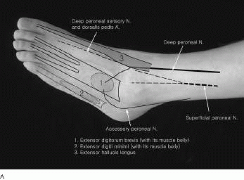 Figure 4-1. A: Anatomy of the dorsum of the foot. B: Anatomy of the ankle-flexor retinaculum. C: Anatomy of peroneal and tibial nerves at the knee. D: Anatomy of the popliteal fossa and placement of stimulating electrodes. |
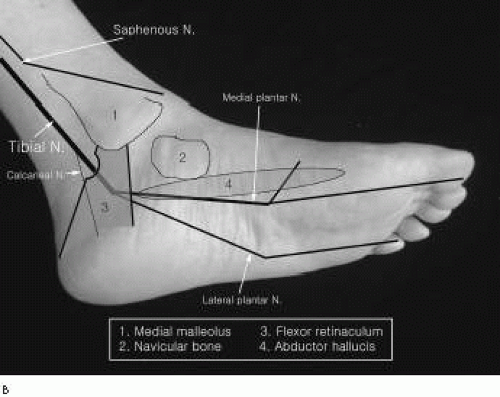 Figure 4-1. (continued) |
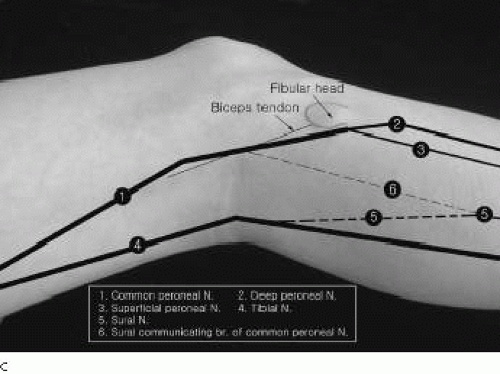 Figure 4-1. (continued) |
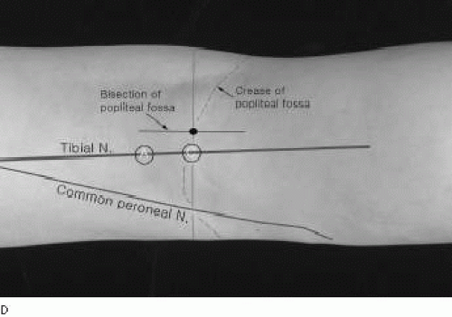 Figure 4-1. (continued) |
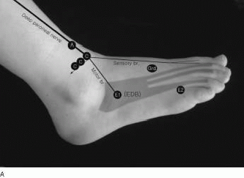 Figure 4-2. A: Peroneal nerve motor conduction to the extensor digitorum brevis. B: Proximal stimulation sites in peroneal nerve motor conduction studies. |
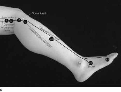 Figure 4-2. (continued) |
Peroneal Nerve Motor Conduction Study1
Recording Electrode Placements
Stimulation
For routine peroneal motor conduction studies, stimulations are applied in three sites.
Ankle: Stimulation is applied 8 cm proximal to the E1, just lateral to the tibialis anterior tendon. At times, high intensities of current are required to stimulate the nerve because it is deep beneath the tendon, thick skin, or edema. Occasionally, the nerve is displaced more laterally so the stimulating cathode needs to move laterally to the nerve’s close proximity.
Below fibular head: The nerve is stimulated just below and lateral to the fibular head.
Knee: The stimulation is applied at the cross-section point between the lateral hamstring tendon and crease of the popliteal fossa. Proximal to this point, it is often difficult to stimulate because the nerve is positioned more deeply under the biceps femoris tendon. Stimulation applied more proximal to the popliteal fossa may excite both the peroneal and tibial nerves because of both nerves’ close proximity.
Reference Values
Amplitude [millivolts (mV)] | |||
|---|---|---|---|
A-BFH | AFH | Conduction velocity [meters per second (m/s)] | |
4.5 ± 0.8 | 4.4 ± 1.0 | 51.6 ± 4.1 | 53.9 ± 4.3 |
Comments
While stimulating the nerve at the ankle, it is recommended that the cathode be applied just above the extensor retinaculum, considering the anterior tarsal tunnel syndrome, although it is rare.
Accessory Peroneal Nerve Conduction Studies
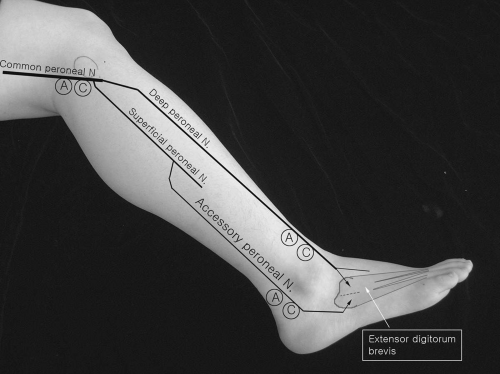 Figure 4-3. Accessory peroneal nerve conduction studies. |
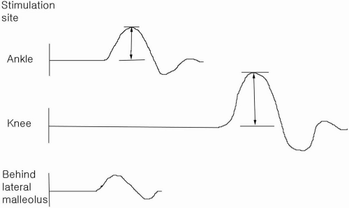 Figure 4-4. Accessory peroneal nerve conduction studies. A part of the extensor digitorum brevis muscle is innervated by the accessory peroneal nerve. |
Anomalous innervation to the extensor digitorum brevis occurs approximately 20% of the time. The accessory peroneal nerve, an extension of superficial peroneal nerve, courses posteriorly and under the lateral malleolus, where stimulation is applied. It is indicated by a different (smaller) compound muscle action potential (CMAP) (partial anomaly) or an absence of a CMAP (complete anomaly) when stimulating the deep peroneal nerve distally at the ankle.
Peroneal Motor Conduction Study to the Tibialis Anterior
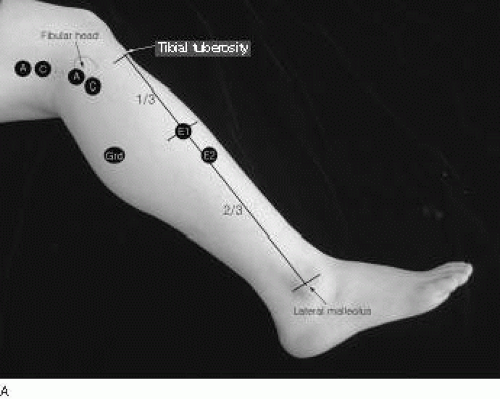 Figure 4-5. A: Peroneal motor nerve conduction studies to the tibialis anterior (Devi et al).2 B: Peroneal motor nerve conduction studies to the tibialis anterior and peroneous longus (Lee et al.)3 |
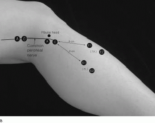 Figure 4-5. (continued) |
Tibialis Anterior Recording (Devi et al.)1
E1 The E1 electrode is placed at the junction of the upper one-third and lower two-thirds of a line between the tibial tuberosity and the tip of the lateral malleolus of the fibula.
E2 The E2 electrode is placed over the medial aspect of the tibia, 4 cm distal to the active electrode.
Stimulation
The stimulation is applied below the head of the fibula and the popliteal fossa along the medial border of the biceps femoris tendon with about 10 cm between the two points of stimulation.
Peroneal Motor Nerve Conduction to the Tibialis Anterior and Peroneus Longus (Lee et al.)3
Tibialis Anterior
Peroneus Longus
Stimulation Sites
Fibular neck, below fibular head.
Popliteal fossa
Reference Values
To tibialis anterior | Below fibular head | Above fibular head |
|---|---|---|
Latency (ms) | 3.0 ± 0.6 | 4.7 ± 0.5 |
Conduction velocity across the fibular head, 66.3 ± 12.9 (m per s)
Distance from point of stimulus to the E1 was not specified. Skin temperature also was not specified. However, the room was kept at a constant temperature of 22.2°C to 23.3°C.
Recording site | Latency (ms) | Amplitude (mV) |
|---|---|---|
Tibialis anterior | 2.5 ± 0.3 | 6.2 ± 1.3 |
(3.6 to 9.3) | ||
Peroneus longus | 2.6 ± 0.2 | 6.2 ± 1.4 |
(3.4 to 10.6) |
Comments
Peroneal motor conduction to the tibialis anterior may be useful to assess the electrophysiogic abnormalities of the peroneal nerve when the motor response is absent because of severe atrophy of the extensor digitorum brevis. In common peroneal neuropathy at the knee, the superficial peroneal nerve often is less involved than the deep peroneal nerve. Thus, the CMAP recorded from the tibialis anterior may be a part of a volume-conducted response from the adjacent peroneus longus.
Peroneal Motor Nerve Conduction Across the Knee: Short Segment Stimulation
(Fig. 4-6)
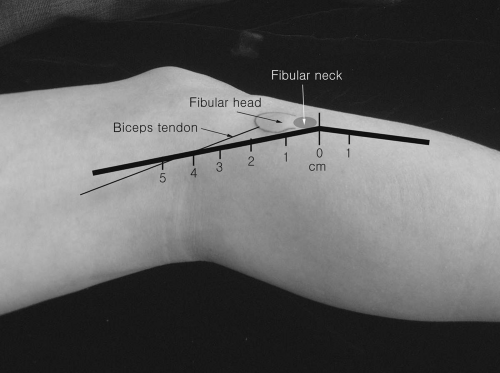 Figure 4-6. Short segment incremental stimulation (SSIS) of the peroneal nerve across the fibular head. |
Recording Electrode Placement
E1 The E1 is placed over the belly of the extensor digitorum brevis.
E2 The E2 electrode is secured over the metatarsophalangeal joint of the little toe.
Stimulation
Stimulation is applied at 2-cm intervals along the path of the peroneal motor nerve across the fibular head.
Superficial Peroneal Nerve Sensory Conduction
(Fig. 4-7)
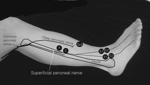 Figure 4-7. Superficial peroneal nerve sensory conduction studies. |
Recording Electrode Placements
The intermediate branch of the superficial peroneal nerve can be studied with E1 and E2 electrodes embedded in a plastic bar 1 to 2 cm medial to the lateral malleolus at the ankle. Slight repositioning of the bar electrode toward the tibialis anterior tendon may record the medial branch.
Stimulation
The stimulation is applied 12 to 14 cm proximal to the E1 electrode, just anterior to the anterior edge of the fibula. Occasionally, the stimulator may have to be firmly pressed against the skin. Slight repositioning of the original stimulation point proximally or distally may be required to elicite the optimal sensory response.
Deep Peroneal Sensory Nerve Conduction Studies
(Fig. 4-8)
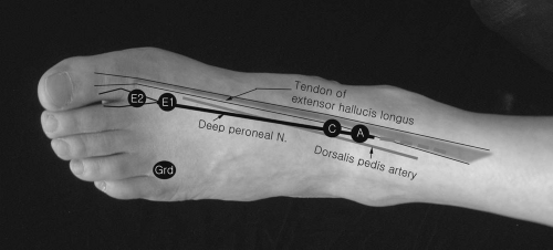 Figure 4-8. Deep peroneal sensory nerve conduction studies. |
Recording Electrode Placements
E1 and E2 The E1 and E2 electrodes embedded in a plastic bar are placed at the first web space between the first and second metatarsal bones on the dorsum of the foot.
Stimulation
Reference Values
Latency (ms) | |||
|---|---|---|---|
Onset | Peak | Amplitude (μV) | Conduction velocity (m/s) |
2.9 ± 0.4 | 3.6 ± 0.4 | 3.4 ± 1.4 | 42 ± 5 |
Amplitude (μV) | |
|---|---|
3.2 ± 0.5 | 5.2 ± 0.5 |
Comments
Because of the short distance between the stimulating and recording electrodes, shock artifacts are common in conduction studies. Applying small electric currents [e.g., 5 to 10 milliamperes (mA) with 0.1-ms pulse duration] and rotation of anode are often helpful. Occasionally, repositioning the cathode slightly lateral to the original stimulation point may enhance eliciting the sensory response because the nerve and dorsalis pedis artery may be displaced more laterally. A monopolar needle electrode (E1) with surface reference electrode (E2) can also be used. A side-to-side comparison is helpful.
Peroneal Mixed Nerve Conduction Across the Fibular Head
(Fig. 4-9)
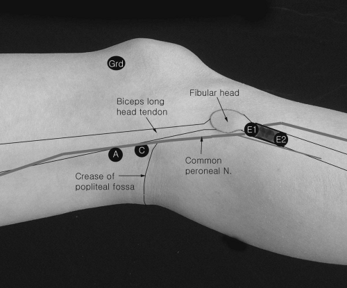 Figure 4-9. Peroneal mixed nerve conduction studies across the fibular head. |
Recording Electrode Placements
E1 and E2 electrodes embedded in a plastic bar are secured below and anterior to the fibular neck area.
Stimulation
The stimulation is applied at the intersection between the medial border of the biceps long head tendon and the popliteal crease.
Reference Values
Subject: 35 (70 nerves)
Amplitude (μV) | Conduction velocity (m/s) | |
|---|---|---|
Right | 24.8 ± 7.4 | 61.6 ± 4.5 |
Left | 23.3 ± 6.9 | 61.7 ± 4.3 |
Values are means ± SD
Comments
Because of a short distance between the stimulating and recording electrodes, shock artifacts are troublesome. The recording electrodes are secured firmly with a wraparound Velcro strap.
Lateral Cutaneous Nerve of Calf Conduction Studies (Sural Communicating Branch of Common Peroneal Nerve)
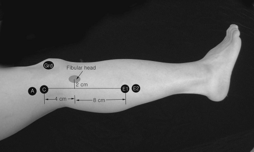 Figure 4-10. Lateral cutaneous nerve of the calf (sural communicating branch of common peroneal nerve) conduction studies. |
Recording Electrode Placements and Stimulation
Stimulation
A mark is made on the skin 2 cm behind the center of the fibular head and another is made 4 cm proximal to the first mark point.
E1 and E2 The E1 and E2 electrodes embedded in a plastic bar are placed 12 cm distal to the stimulation site in a line connecting the stimulation point and the tip of the calcaneus. Orthodromic conduction studies are also performed with the stimulating and recording electrodes were switched.
Reference Values9
Latency (ms) | |||
|---|---|---|---|
Onset | Peak |
||


