Instrumentation
Sanjeev D. Nandedkar
Introduction
The primary function of an electromyograph is to record, amplify, and display a low-amplitude neurophysiologic signal in the presence of high-amplitude ambient noise and interference. The term “noise” usually refers to the internal noise that is inherent in all electronic devices. “Interference” represents the potentials introduced from the surrounding environment (e.g., radio and TV transmissions). For simplicity, we will refer to both phenomena as noise. The electromyograph can selectively amplify the nerve and muscle potentials while attenuating the ambient noise. This is described as improving the signal to noise (S/N) ratio. In modern instruments the S/N ratio is increased by developing sophisticated hardware and software. The hardware refers to physical devices such as amplifier and cables. The software represents signal-processing algorithms that are executed using personal computers. The design and specification of each of these components affects the noise as well as the signal of interest. Hence, it is important to understand the role of instrumentation in electrodiagnostic examination (EDX). This expertise also allows one to conduct studies in hostile environments, recognize artifacts, and perform studies in a fast and efficient manner.
In this chapter we will review the hardware and software components of a typical commercially available electromyograph. It is not our intention to review sophisticated signal-quantitation algorithms. Nevertheless, we will discuss the basic strategy in making measurements manually. One must be able to recognize failure of automated algorithms, which occurs quite frequently.
Electrodes
The electrodes are sensors that detect electrical potentials generated by the nerves and muscles. For good recordings, there should be a good contact between the signal generators and the recording electrodes. This is described as having “low electrode impedance.” In EDX, the intramuscular needle electrodes are surrounded by highly conductive body fluids. This gives a good contact (i.e., low impedance). In contrast, the surface electrodes are placed on skin and make a poor contact to the body (i.e., they have high impedance). The impedance of surface electrodes is reduced using many simple strategies.
First, the skin surface at recording site is cleaned using alcohol-soaked pads. Lotions and perfumes are poor conductors of electricity, and these are removed by the cleaning process. A mild abrasive may be used to remove the dead skin cells, which have high resistance to electricity. Finally, electrolytic gel is used to improve the contact between the electrode and skin. The impedance measurements are often mandatory in evoked potential (EP) and electroencephalography (EEG) recordings, where one aims to obtain
an impedance of 4 kilo-ohms or even less. Furthermore, the impedance of all recording electrodes should be similar (1).
an impedance of 4 kilo-ohms or even less. Furthermore, the impedance of all recording electrodes should be similar (1).
Reusable surface electrodes should be washed thoroughly to remove any build-up of residues of the electrolytic gel. Reusable needle electrodes should be inspected under a microscope for the presence of burs and hooks, which cause significant pain during needle insertion and movement. These are removed by polishing the needle tip. Special electrodes such as those used in single-fiber EMG may require electrolytic treatment. The details of this procedure can be obtained from the needle manufacturers.
Leads and Cables
A lead is piece of wire that connects the recording electrode to the amplifier. A collection of leads makes a cable. A lead is a piece of wire, just like an antenna. Hence, the lead also behaves as a recording electrode, except that it registers noise and interference. Increasing the length of the lead will record more noise. Hence, the length of lead should be kept as small as possible. As described later, it is desirable that all leads record the same ambient noise. This is accomplished by weaving the leads into one another to form a cable. Such cables containing only two leads are often called the “twisted pair” leads. Surface electrodes used for nerve conduction studies are commercially available in straight and twisted leads. Shielded cables are useful when a long cable length is necessary. The shielding reduces the interference recorded by the leads contained in them.
All EMG recordings require three electrodes (described later). Their leads are color-coded by most manufacturers as Red for Reference (E2), Green for Ground, and Black for the Active (E1) electrode. In past the leads terminated into 2- or 4-mm pins that were inserted into the amplifier receptacle. A few years ago, the U.S. Food and Drug Administration (FDA) mandated that all leads must be “touch-proof” to improve patient safety. Users of old equipment are urged to convert their EMG instruments and accessories to meet the FDA guidelines.
Amplifier
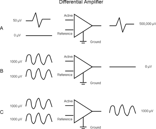
This is the most important component of the electromyograph. The amplifiers used in consumer electronic devices (e.g., radio, TV) need two input connections. In contrast, EMG amplifiers require three connections: active, reference, and ground (Fig. 5-1). The amplifier does not magnify the signals at individual inputs; rather, it magnifies the potential difference between the active and reference inputs. Hence, it is called a differential amplifier. The use of differential amplification allows us to improve the S/N ratio. In Figure 5-1A, the active electrode is a monopolar needle and records a fibrillation potential of 50 μV. The reference electrode is electrically silent. Their difference is amplified to obtain an output signal of 500,000 μV (or 0.5 Volts). The differential gain of the amplifier is thus 500,000/50 = 10,000.
At the same time, there is an ambient noise of 1,000 μV. However, this noise is identical at the active and reference inputs (see Fig. 5-1B). Their difference is zero, and hence we do not see it at the amplifier output. In this manner we can record the low-amplitude electromyographic potentials in presence of high-amplitude noise.
The concept of noise attenuation in Figure 5-1B is an idealized viewpoint. Real differential amplifiers do amplify the signals that are common (i.e., identical) to active and reference input. In Figure 5-1C, we find noise amplitude to be 1,000 μV at the amplifier output. The amplification of common signals is called the common gain, and in Figure 5-1C it is equal to 1. Note that the S/N ratio at amplifier input and output is 0.05 and 500, respectively. For the best performance, the amplifier should have a high differential gain (see Fig. 5-1A) and a low common mode gain (see Fig. 5-1C). These properties are described by a single characteristic called the common mode rejection ratio (CMRR):
CMRR = Differential gain/Common mode gain
Engineers prefer to describe the CMRR in units of decibels (dB) using the formula:
CMRR (dB) = 20 log (Differential gain/common mode gain)
 Figure 5-1 • Differential amplifier. A. EMG signal appears as differential input and has a gain of 10,000. B. Noise is identical at active and reference inputs. C. The common mode gain is 1. |
In the schematic amplifier of Figure 5-1, the CMRR is 100 dB. Modern commercially available amplifiers have a CMRR of 100 dB or better.
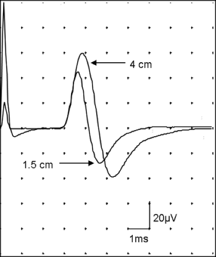
In Figure 5-1A, we assumed that reference electrode does not register any electrical activity. In EMG and nerve conduction studies (NCS), this is not true. The cannula of a single-fiber EMG records motor unit activity called the “macro EMG” motor unit potential (MUP) (2). In motor NCS, the position of the reference electrode affects the initial deflection of the compound muscle action potential (CMAP) (3). In sensory NCS, the nerve action potential passes under active and reference electrodes. The sensory nerve action potential (SNAP) depends on the distance between the active and reference electrodes. Short distance will give a lower amplitude and a shorter peak latency (Fig. 5-2). Hence, one should use a standard separation between the active and reference electrodes. Most laboratories use a 2- to 4-cm distance. Using a bar electrode in a sensory NCS results in standardized separation of E1 and E2.
The amplifier is also characterized by its input impedance. In contrast to the recording electrodes, the input impedance of the differential amplifier should be high. Low-input impedance attenuates the physiologic potential. Fortunately, modern amplifiers have very high impedance (>1,000 Ω) and do not pose any problems for this requirement.
 Figure 5-2 • SNAP is recorded with active-reference electrode separation of 4 cm and 1.5 cm. Signal from the reference electrode affects the amplitude and peak latency. |
When the electrode leads are in close spatial proximity, they should record similar ambient noise. By virtue of differential amplification, this noise will be attenuated. Hence, twisted paired leads or shielded cables are recommended in a hostile environment (e.g., the intensive care unit).
If the recording electrodes have different impedances, the noise they record is slightly different at the amplifier inputs. This imbalance gives higher noise despite differential amplification. It is typically seen in monopolar needle EMG recordings where the active recording electrode is intramuscular with low impedance. The reference electrode placed on the skin surface has higher impedance. Higher noise in monopolar EMG can also result due to spatial separation among the leads of the needle and surface electrodes.
Filters
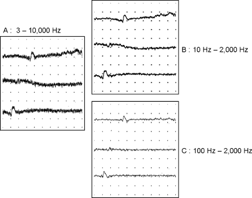
All EMG amplifiers use a “bandpass” filter to attenuate noise. The filters can be hardware devices or signal-processing algorithms implemented in software. The algorithms are called digital filters. The bandpass filter is characterized by two frequency settings: low and high. Their effect on EMG signal (Fig. 5-3A) can be understood easily from the sound of EMG on the audio monitor. Adjusting the high-frequency setting is the same as changing the treble control on a tape or CD player. When the high-frequency setting is reduced, the “hiss” decreases. The high-frequency noise is reduced (see Fig. 5-3B). Changing the low-frequency setting is the same as adjusting the bass control. Increasing the low-frequency setting attenuates the sound of instruments like a tuba or drum. On EMG, the baseline is stabilized and it appears “clamped” near the center of the display (middle trace in Fig. 5-3A,B,C). By reducing the bandwidth (i.e., increasing the low-frequency and/or decreasing the high-frequency setting), the noise and interference are reduced. The signal is also affected. Hence, it is necessary to understand the effect of filters on EMG waveforms.
The needle EMG signals are recorded with a low-frequency setting of 10 to 20 Hz. The high-frequency setting is 10 kHz. When a potential changes rapidly, it is rich in high-frequency components. This is seen in the spike component of the MUP (Fig. 5-4A). Reducing the high-frequency setting decreases the signal amplitude and increases its rise time. The peaks appear rounded rather than sharp (see Fig. 5-4B). The initial and terminal parts of the MUP change slowly. This gives the low-frequency components of the signal. Increasing the low-frequency setting will attenuate the initial and terminal slow components, thus reducing the MUP duration (see Fig. 5-4C).
In sensory nerve conduction studies the low-frequency setting is 10 to 20 Hz. The high-frequency setting is variable. Some laboratories set the high frequency at 10 kHz. This gives a SNAP with higher amplitude and shorter peak latency (Fig. 5-5). Since the baseline appears “noisy,” other laboratories set the high-frequency setting to a lower value (e.g., 2 kHz). This gives a “smooth” waveform with reduced amplitude and longer peak latency (see Fig. 5-5). The onset latency is not significantly affected.
Long duration potentials such as the CMAP are rich in low-frequency components. Therefore, increasing the low-frequency setting reduces the CMAP amplitude (Fig. 5-6). The onset latency
may be slightly longer due to reduced signal amplitude. The duration and area of negative peak are reduced too. The terminal part of the CMAP is distorted, and one observes an extra negative phase at the end of CMAP. Decreasing the high-frequency setting does not significantly affect the CMAP.
may be slightly longer due to reduced signal amplitude. The duration and area of negative peak are reduced too. The terminal part of the CMAP is distorted, and one observes an extra negative phase at the end of CMAP. Decreasing the high-frequency setting does not significantly affect the CMAP.
 Figure 5-3 • Principle of signal filtering. A. Low-amplitude signal with low- and high-frequency noise. B. Reducing the high-frequency setting attenuates the high-frequency noise. C. Increasing the low-frequency setting stabilizes the baseline.
Stay updated, free articles. Join our Telegram channel
Full access? Get Clinical Tree
 Get Clinical Tree app for offline access

|


