Hip Arthroscopy: The Supine Position


Hip Arthroscopy: The Supine Position


Christopher M. Larson

Corey A. Wulf


There has been increased interest in the area of hip arthroscopy over the past decade. Increasing numbers of surgeons are performing or considering incorporating hip arthroscopy into their practice. There is a steep learning curve when performing hip arthroscopy that even the most experienced hip arthroscopists continue to climb. It is imperative to develop consistent and predictable techniques that allow for safe and effective management of hip disorders through the central and peripheral compartment. Patient positioning is the starting point when optimizing various techniques for hip arthroscopy. Hip arthroscopy can be performed in either the supine or the lateral position. This chapter will describe hip arthroscopy in the supine position with a focus on patient position, portal placement, techniques to improve visualization, and the use of intraoperative fluoroscopy in an attempt to optimize surgical techniques and ultimately patient outcomes.


ANESTHESIA

In order to achieve appropriate distraction for work in the central compartment, an adequate motor block is necessary when performing hip arthroscopy. General anesthesia is the most common anesthetic approach and reliably allows for adequate distraction and muscle paralysis if necessary. Most patients undergoing hip arthroscopy are relatively young and general anesthesia is safe and efficient. Spinal anesthesia can also be utilized as long as an adequate motor blockade is achieved. Infrequently, if traction is difficult with spinal anesthesia, a general anesthetic may need to be administered during the case. There are no studies evaluating other regional blocks (i.e., lumbar plexus blocks, sacral plexus blocks, obturator blocks, and lumbar paravertebral blocks) as the sole form of anesthesia during hip arthroscopy.

There is a variable level of postoperative pain seen after hip arthroscopy and the most patients are discharged on an outpatient basis with the use of a local anesthetic at the conclusion of the procedure. Occasionally, there may be patients who have a history of poor pain tolerance or who experience severe postoperative pain in the recovery room after hip arthroscopy. In these patients, a regional block can be considered. Regional blocks that may be helpful in these situations include lumbar plexus blocks, combined lumber plexus and sacral plexus blocks, L1 and L2 paravertebral blocks, and obturator and psoas compartment blocks (1, 2 and 3). There are, however, no large series evaluating the efficacy of these regional blocks for pain after hip arthroscopy.


EXAMINATION UNDER ANESTHESIA

Patient positioning in the supine position does have some advantages when compared with the lateral position. The supine position simplifies positioning at the beginning of the procedure and is user friendly for the anesthesia team (4, 5 and 6). The supine position may also decrease the rarely reported risk of intra-abdominal fluid extravasation when compared with the lateral position. Ultimately, the choice of position to be used during hip arthroscopy is based on surgeon preference, experience, and neither the supine nor the lateral position has proven to be superior to the other.


Basic Setup

Hip arthroscopy requires traction, which can be achieved with the use of a standard fracture table or with commercially available distraction devices designed for hip arthroscopy. We prefer to use a standard fracture table. We believe that the operating room staff’s familiarity with the fracture table aids in efficient setup and eases their ability to adjust the table throughout the case if needed.

The patient is placed in the supine position with care taken to pad all bony prominences. Initially an examination under anesthesia is performed to assess range of motion (ROM). This is particularly useful in cases of femoroacetabular impingement (FAI) and adhesive capsulitis. For these specific cases, ROM, in particular internal rotation and flexion/abduction/external rotation deficits, can be assessed preoperatively and
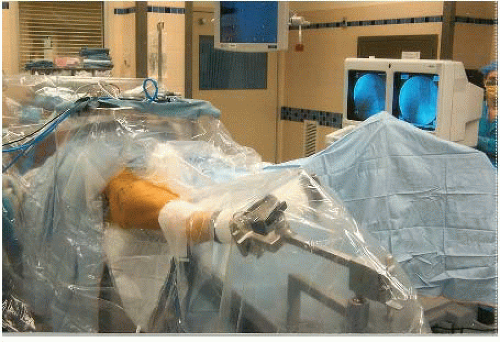
improvements assessed at the completion of the procedure. The patient is then moved distally on the table until contact is made between the medial thigh of the operative leg and the perineal post. The peroneal post should be adequately padded to decrease the risk for local neural and cutaneous injuries. The feet are placed in a well-padded boot or wrapped in cast padding after applying an ABD pad to the dorsomedial aspect of the forefoot. Padding protects the foot from skin and nerve pressure injuries as the feet need to be secure to avoid inadvertent slippage and loss of traction during the case. The feet are placed in the traction boots and further secured with cloth tape. The nonoperative leg is then maximally abducted and externally rotated with the knee in extension. The operative leg is positioned in neutral abduction, neutral to 15° of hip flexion, maximal internal rotation, and full knee extension. The pelvis is leveled by rotating the bed (typically toward the operative side) until the anterior superior iliac spines (ASIS) are at the same height and parallel to the floor/ceiling. A mayo stand is brought in from the contralateral side of the patient and placed over the upper torso and head. This acts as a working platform where instruments are easily accessed by the surgeon or assistant while allowing a working space under the surgical drape for the anesthesiologist. Finally, the video monitor is placed at the patient’s head, next to fluoroscopic monitor (Fig. 46.1).


Intraoperative Fluoroscopic Evaluation

Although some surgeons routinely perform hip arthroscopy without intraoperative imaging, we find fluoroscopic guidance to be very useful. Intraoperative fluoroscopy aids in safe portal placement, maintenance of correct orientation throughout the surgical procedure, and evaluation of bony resections when indicated.

The fluoroscopy machine (C-arm) is brought in between the patients’ lower extremities at an angle of 45° to the neutrally abducted operative leg (Fig. 46.2). The base can be locked in place and the arm telescoped in and out, so as not to interfere with the manipulation of instruments while allowing the surgeon to efficiently obtain imaging when necessary.


FIGURE 46.1. Hip arthroscopy setup in the supine position (right hip).

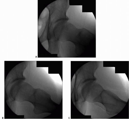
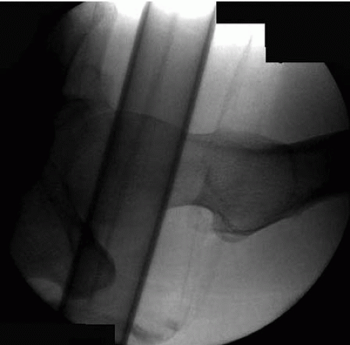
We perform a fluoroscopic evaluation of the hip prior to draping or distraction. An anteroposterior (AP) view of the hip is initially obtained to verify neutral abduction of the leg and correct rotation of the pelvis. Variable degrees of abduction or adduction of the operative leg may be required based on trochanteric height and acetabular inclination. The pelvic rotation can be estimated as noted in the previous section and verified radiographically by aligning the coccyx and pubic symphysis. There should be approximately 0 to 3 cm between the tip of the coccyx and symphysis in the cranial to caudal plane for neutral pelvic tilt. The goal is to obtain an intraoperative fluoroscopic view identical to a well-aligned preoperative AP radiograph of the patient’s pelvis. The anterior and posterior walls are identified, allowing the surgeon to identify any area of rim resection (RR) that has been planned or templated on preoperative radiographs. Next, the femoral head-neck junction (FHNJ) is evaluated with an “around-the-world” inspection (7). With the hip in extension, fluoroscopic images are obtained in maximal hip internal rotation, neutral rotation, and maximal external rotation (Fig. 46.3). This provides assessment of the superior and inferior head-neck junction corresponding to the preoperative AP radiograph. Next, the hip is evaluated in 45° of hip and knee flexion. This is performed with the foot in the traction boot and allowing the entire bracket to slide proximally. Fluoroscopic images are obtained in maximal hip internal, neutral, and maximal external rotation (Fig. 46.4). This allows for inspection of the anterior and posterior head-neck junction corresponding to preoperative lateral radiographs. The neutral image (greater trochanter in line with the femoral neck (FN)) with the hip in flexion is similar to a modified Dunn view. We also obtain a cross-table lateral to assess femoral version
and complete the evaluation of the head-neck junction (Fig. 46.5). Finally, the operative leg is brought back to the “starting position” (neutral abduction, hip flexion of 15° to 20°, full-knee extension, and maximal internal rotation) and traction is applied until adequate distraction of the FH is achieved (Fig. 46.6). In some cases, breaking the seal may be difficult to achieve and gently shaking the hip along with IR and ER of the foot typically achieves atraumatic release of the intra-articular seal in these cases. If the seal is still difficult to release, excessive traction should be avoided and the use of a spinal needle at the beginning of the case will allow for an atraumatic release of the seal. The traction is then released while the leg is prepped and draped to minimize traction time.


FIGURE 46.2. Fluoroscopy machine brought in between the legs during the supine approach (left hip).


FIGURE 46.3. Fluoroscopic images intraoperatively with the hip in extension and (A) internal rotation, (B) neutral rotation, and (C) external rotation (left hip).


Draping

The thigh and groin are prepped from the ASIS proximally to the knee distally. The entire posterior and lateral aspect of the thigh is also prepped medially to the perineal post. A sterile down drape is placed over the nonoperative leg. A second sterile down drape is placed over the mayo stand and extended just proximal to the ASIS. The surgical landmarks (ASIS and greater trochanter) are identified and marked with a surgical marker. A hip fracture drape is then adhered to the thigh and pulled over the operative leg and abdomen (Fig. 46.1). This transparent hip fracture drape is invaluable for hip arthroscopy, allowing for visualization of the traction apparatus and ease of manipulation of the leg during the procedure.


FIGURE 46.4. Fluoroscopic images intraoperatively with the hip in flexion and (A) internal rotation, (B) neutral rotation, and (C) external rotation (left hip).


Specialized Instrumentation

Instruments specifically designed for hip arthroscopy are available through multiple vendors. Specifically designed instrumentation (baskets, punches, curettes, microfractures awls, suture passers, and graspers) improves the ease and safety with which hip arthroscopy is performed. In addition to an arthroscopic hip set, our standard instrumentation includes a slotted cannula, an extended length burr and curved shaver, a flexible tissue ablation probe, and a long-handled, curved beaver blade (BB).


PORTAL PLACEMENT AND ANATOMY

Exposure is essential to the success of any surgical procedure. Portal placement is the equivalent of exposure for arthroscopic surgery. Correct portal placement allows maximal visualization, reduced risk for iatrogenic injuries to intra-articular or neurovascular structures, and effective manipulation of instrumentation. The placement of arthroscopic portals about the hip poses unique challenges. The relatively thick soft tissue envelope restricts palpation of the osseous articular structures and joint space commonly used in portal placement for other joints. The highly constrained three-dimensional structure of the hip restricts intra-articular placement without significant distraction. Finally, the reduced volume of the capsule in a distracted hip provides a very little working space in the peripheral greater than central compartments. Despite these challenges, techniques for portal placement have evolved to allow for
safe placement and adequate visualization of the central, peripheral, and peritrochanteric compartments of the hip.
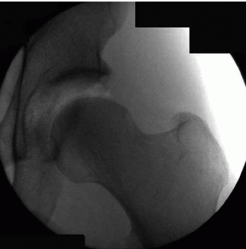


FIGURE 46.5. Cross-table lateral fluoroscopic image of the hip intraoperatively (left hip).


FIGURE 46.6. Intraoperative fluoroscopic image of the hip in traction verifying adequate distractibility (left hip).

There have been multiple portals described for treatment of both intra-articular and extra-articular pathologies about the hip (8, 9 and 10) (Tables 46.1 and 46.2). The knowledge and use of multiple portals allow the surgeon to address a vast array of pathology. In the author’s experience, two to three standard portals provide adequate access for most cases, with accessory portals used when necessary. A clear understanding of the anatomic relationships between portals and important structures reduces the risk of injury. All described portals are placed in reference to key superficial anatomical structures: the anterior superior iliac spine and greater trochanter. Both structures are palpated and marked with a surgical marker for easy referencing during the procedure. It is important to acknowledge the variability from patient to patient with respect to neck-shaft angle, the height of the greater trochanter, FN version, and acetabular inclination. The individual variations may require the surgeon to adjust portal placement and/or leg position in order to maintain maximal visualization.


Anterolateral Portal

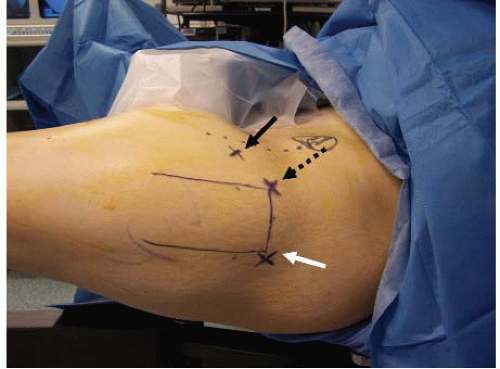
The anterolateral (AL) portal (anterior paratrochanteric portal) is placed approximately 1 cm anterior and 1 cm superior to the tip of the greater trochanter (9) (Fig. 46.7). The typical trajectory is 15° cephalad and 15° posterior (10). This portal takes advantage of the interval between the tensor fascia lata (TFL) anteriorly and the gluteus maximus posteriorly (10), before piercing the gluteus medius muscle belly and entering the lateral aspect of the joint capsule. The AL portal is a relatively safe portal. The superior gluteal nerve poses the biggest risk of neurologic injury, but lies safely 4 to 6 cm superior. The nerve passes posterior to anterior, deep to the gluteus medius muscle after exiting the greater sciatic notch. Iatrogenic injuries to the FH or labrum pose the largest overall risk.


Posterolateral Portal

The posterolateral (PL) portal (posterior paratrochanteric portal) is established in a similar manner to the AL portal, but on the posterior aspect of the trochanter. The portal is placed 1 cm posterior and 1 cm superior to the tip of the greater trochanter (Fig. 46.7) (9). A spinal needle is directed medially with a trajectory of 5° cephalad and 5° anterior (10). The portal pierces the gluteal fascia, gluteus medius, and gluteus minimus muscle bellies
before entering the lateral aspect of the posterosuperior capsule. Byrd (11) described the portal as coursing superior and anterior to the piriformis muscle tendon prior to entering the capsule. However, Robertson and Kelly (10) found that the PL portal passed through the piriformis tendon. This discrepancy may be due to the slight variation in the two authors’ portal placement.


FIGURE 46.7. Intraoperative image of the left hip depicting the typical anterior (black solid arrow), AL (black dashed arrow), and PL (white arrow) portals. A circle outlines the ASIS, and the greater trochanter is outlined with a surgical marker.


Table 46.1 Distance from portal to anatomic structures


Portal


Anatomic Structure


Average (cm)


Range (cm)


Anterior


Anterior superior iliac spinc


6.3


6.0-7.0


LFCNa


0.3


0.2-1.0


Femoral nerve


Level of sartoriusb


4.3


3.8-5.0


Level of rectus femoris


3.8


2.7-5.0


Level of capsule


3.7


2.9-5.0


Ascending branch of lateral circumflex femoral artery


3.7


1.0-6.0


Terminal branchc


0.3


0.2-0.4


Anterolateral


Superior gluteal nerve


4.4


3.2-5.5


Posterolateral


Sciatic nerve


2.9


2.0-4.3


a Nerve had divided into three or more branches and measurement was made to closest branch.

b Measurement made at superficial surface of sartorius, rectus femoris, and capsule.

c Small terminal branch of ascending branch of lateral circumflex femoral artery identified in three specimens.


From Byrd JW, Pappas JN, Pedley MJ. Hip arthroscopy: an anatomic study of portal placement and relationship to the extra-articular structures. Arthroscopy. 1995;11:418-423, with permission.

Only gold members can continue reading. Log In or Register to continue

Stay updated, free articles. Join our Telegram channel

Jul 22, 2016 | Posted by in ORTHOPEDIC | Comments Off on Hip Arthroscopy: The Supine Position

Full access? Get Clinical Tree
Get Clinical Tree app for offline access