Circular External Fixation Components and Design Considerations
Paul S. Cooper
Introduction
A thorough knowledge of the many components that are involved in external fixation design and pin/wire attachment significantly facilitates application of an external fixator to the lower extremity. In general, there is no limitation to the imagination on what an external fixator can perform; this has to be balanced with the time constraint of construction and application. The vast majority of foot and ankle cases can be addressed with a core selection of circular external fixation components.
Circular External Fixation Components
Circular Rings, Half Rings and Foot Plates
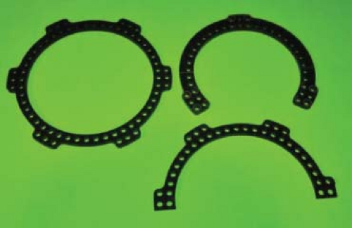
The components that make up circular external fixation can be divided into rings, ring connectors, and fixation hardware. Rings are either partial (one-half or five-eighths) or full in geometry (Figure 4.1). While full size rings are typically applied to the tibia, if postoperative swelling occurs, the ring may need to be cut off or the circular external fixator taken apart. Two half rings connected with bolts avoid this complication. Half rings may be also used in conjunction with the foot ring and complete their attachment with the tibial circular ring fixation. Five-eighths rings are typically used either in the proximal tibia to allow for knee flexion or distally at the ankle joint open anteriorly.
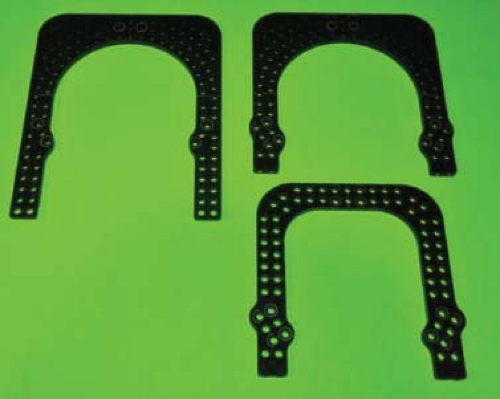
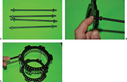
External fixation foot rings are usually “U” shaped in configuration with variable length arms (Figure 4.2). In order to maximally tension wires off the foot ring, the open front end needs to be closed off (Figure 4.3). This can be usually accomplished by adding a half ring at 90 degrees to the foot ring or to what is referred by many as the foot plate (Figure 4.4A–C).
Threaded Rods, Telescoping Rods, and Struts
Rings are connected into segments or blocks by several methods. The simplest method to build a two or more ring block
assembly is with threaded rods and nuts. A minimum of three points dispersed evenly around the ring is recommended; four points confer additional stability of the block (Figure 4.5). Standard threaded rods are useful in static “tibial block” configurations where no movement or activity through the block is needed (Figure 4.6A–C). Rings can alternatively be connected with variable length struts of threaded sockets or rancho cubes. These sockets and cubes can be threaded together with various lengths of threaded rods (Figures 4.7A–C).
assembly is with threaded rods and nuts. A minimum of three points dispersed evenly around the ring is recommended; four points confer additional stability of the block (Figure 4.5). Standard threaded rods are useful in static “tibial block” configurations where no movement or activity through the block is needed (Figure 4.6A–C). Rings can alternatively be connected with variable length struts of threaded sockets or rancho cubes. These sockets and cubes can be threaded together with various lengths of threaded rods (Figures 4.7A–C).
 Figure 4.3. Examples of external fixation plates with enclosed ends and crossbars for anterior to posterior wire placement. |
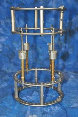
Motion required between ring blocks can be broken down into single (longitudinal) or multiplanar motion. Longitudinal motion is needed in compression (arthrodesis) cases or distraction osteogenesis (limb lengthening) (Figure 4.8). The simplest way to axially compress or distract between two ring blocks is with a threaded rod and a compression/distraction nut. The four faces on the nut have one to four dots to correspond with quarter turns. One full rotation is the equivalent of 1 mm of travel on the threaded rod, typically recommended in bone transport. An effective alternative are telescoping rods. These devices are pre-assembled with a threaded rod in the core, and by way of slotted windows and incremental marking, allow measurement of travel over time (Figure 4.9). Multiplanar motion between ring
segments may consist of one or more combinations of rotational, translational, sagittal, or coronal plane degrees of freedom. More recently, virtual axis concept of struts moving in an infinite number of planes has been advocated. To address multiplanar correction, a hinged strut is required. These generally combine hinges at the two ends of the strut with a gradual axial lengthening compression/distraction segment in the middle. Newer struts allow for quick release of the strut for fast temporary gross reduction and a locking collar for definitive stabilization (Figure 4.10). Virtual axis struts may be used with software programs to determine a schedule for achieving the desired final correction.
segments may consist of one or more combinations of rotational, translational, sagittal, or coronal plane degrees of freedom. More recently, virtual axis concept of struts moving in an infinite number of planes has been advocated. To address multiplanar correction, a hinged strut is required. These generally combine hinges at the two ends of the strut with a gradual axial lengthening compression/distraction segment in the middle. Newer struts allow for quick release of the strut for fast temporary gross reduction and a locking collar for definitive stabilization (Figure 4.10). Virtual axis struts may be used with software programs to determine a schedule for achieving the desired final correction.
 Figure 4.9. Example of telescoping rods between two tibial block segments allowing axial compression or distraction only.
Stay updated, free articles. Join our Telegram channel
Full access? Get Clinical Tree
 Get Clinical Tree app for offline access

|


