Arthroplasty of the Shoulder Using the Reverse Prosthesis
Brian L. Puskas
Kevin L. Harreld
Deenesh T. Sahajpal
Mark A. Frankle
Historically, the management of patients with irreparable rotator cuff tears and glenohumeral arthritis has been a challenge. Within the last 15 years, the use of reverse shoulder arthroplasty (RSA), a semiconstrained prosthesis, has provided a significant improvement in the management of patients. RSA for cuff tear arthropathy (CTA), proximal humeral fractures with incompetent rotator cuffs, deformity associated with proximal humeral malunion, and failed total shoulder arthroplasty (TSA) has demonstrated reliable improvement in pain and function. Complications related to the use of RSA are well documented and include infection, scapular notching, weak external rotation, limited motion, and loss of deltoid function. Today, an improved understanding of the biomechanics of the RSA, pathological changes associated with rotator cuff-deficient shoulder, and evolution of arthroplasty technology have helped to minimize these complications.
There are several RSA designs available for use, but we describe in detail the surgical technique for the reverse shoulder prosthesis (RSP; DJO Surgical, Austin, Texas). The advantage of a system such as this is the ability to select from a number of glenospheres, which have varying offsets (0 to 10 mm lateral to the glenoid surface), a baseplate with a compression lag screw, and a humeral component of 135 degrees. The option of multiple glenospheres aids in soft-tissue balancing, and the lateral center of rotation increases the impingement-free range of motion and minimizes scapular notching. The central lag screw provides stronger fixation than a central peg and, therefore, is useful in bone deficit scenarios. Finally, a neck-shaft angle of 135 degrees facilitates anatomic reconstruction of the humerus and translates the humerus laterally, further protecting against scapular notching. In addition, Franklin et al. (1) have stated that lateralizing the humerus produces “increased rotator cuff and deltoid lever arms.” Successful use of this surgical technique and RSA has been well documented since 1998.
INDICATIONS/CONTRAINDICATIONS
The indications for RSA include the management of the irreparable rotator cuff with associated glenohumeral arthritis, the irreparable rotator cuff associated with glenohumeral instability, failed hemiarthroplasty, failed TSA associated with rotator cuff deficiency, and the cuff deficiency equivalent, such as ununited or resorbed greater tuberosity segments following fracture. The procedure has several relative contraindications that may not provide predictably improved outcomes. These include patients with a nonfunctional deltoid muscle, patients with an active infection, and cases with excessive bone loss either on the glenoid side or on the humeral side. Severe neurologic deficiencies such as syringomyelia, Charcot joint, or Parkinson disease are relative contraindications due to the increased chance of instability associated with excessive, uncontrolled movements or decreased sensation, resulting in an increased risk for early loosening. Finally, RSA is contraindicated
for patients with a metal allergy, a lack of insight into the procedure, or those who refuse to comply with postoperative activity restrictions.
for patients with a metal allergy, a lack of insight into the procedure, or those who refuse to comply with postoperative activity restrictions.
This chapter describes the technique for the insertion of the primary RSA and outlines the techniques used for the management of more challenging pathologic anatomy and clinical situations. These problems include the following scenarios: eccentric and concentric glenoid-sided bone loss, humeral-sided failure, mild to severe bone loss associated with proximal humerus fracture, and deformity associated with malunion.
PREOPERATIVE PLANNING
A detailed history and physical examination are performed on all patients. The majority of patients with arthritic cuff deficient shoulders are beyond the seventh decade and female. They typically describe a long history of progressively increasing pain in their arm, especially at night, and pain aggravated by glenohumeral motion.
The physical examination may reveal evidence of anterior swelling and excessive fluid in the subacromial space. An assessment of the shoulder range of motion (ROM) often reveals a restriction secondary to weakness, pain, and stiffness. The most obvious weakness is often seen in forward flexion, external rotation, and abduction. The integrity of the subscapularis is important to determine in the preoperative evaluation. Physical examinations include the belly-press test, lift-off test, and an assessment of the passive external rotation of the shoulder. An increase in the passive external rotation in comparison to the normal contralateral side is often observed with a deficient subscapularis.
All patients have radiographs of the shoulder including a true anteroposterior or Grashey view of the glenohumeral joint, an axillary view, and outlet or scapular Y view of the shoulder. The radiographs reveal the degree of degenerative changes in the humerus, glenoid, and acromion. They also demonstrate the position of the humerus relative to the glenoid. Patients also have a computed tomography (CT) scan of the shoulder in order to evaluate the glenoid bone stock and assess the optimal position of the central screw. The axial cuts are used to plan the ideal position of the central screw along the path of the center line. This line describes the central screw as it exits along the anterior scapular neck. The majority of cases allow for the use of this line and typically allow for bone purchase with a screw length of 30 mm (Fig. 40-1A-C). Three-dimensional reconstruction of CT scan may be helpful, particularly in cases of marked bone deformity of glenoid or humerus.
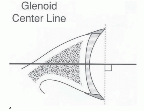 FIGURE 40-1 A: Drill is in place following the center line from the glenoid face. |
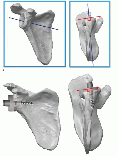 FIGURE 40-1 (Continued) B: Three-dimensional depiction of the glenoid center line. C: A 3-D depiction of the glenoid center line. |
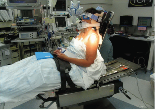 FIGURE 40-2 A patient in a beach-chair position. |
A magnetic resonance imaging (MRI) may be used in the preoperative evaluation of patients. It allows for the evaluation of the supraspinatus, infraspinatus, subscapularis, and teres minor not only in terms of integrity but also degree of muscle atrophy or fat replacement of cuff muscle. Patients with significant deterioration of the external rotators or with involvement extending into the infraspinatus and teres minor complex may be candidates for a latissimus transfer to improve their external rotation.
SURGERY
Positioning
All patients receive appropriate general anesthesia and some may elect to have an interscalene block. Patients are placed in an upright beach-chair position with the head firmly secured and the table is rotated 45 degrees allowing better access to the lateral aspect of the operative extremity. The surgical limb is then draped free after all bony prominences are padded appropriately (Figs. 40-2 and 40-3). The operative arm should be positioned in such a manner as to allow for unobstructed hyperextension and adduction. This is important in order to facilitate glenoid exposure and humeral component insertion. A skin scrub is performed with chlorhexidine gluconate and care is taken to seal off the axilla with a plastic barrier (Fig. 40-4).
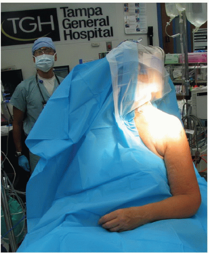 FIGURE 40-3 Head and neck are draped out allowing the shoulder girdle exposed to be scrubbed and prepped. |
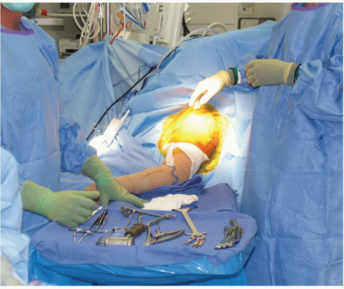 FIGURE 40-4 The operative bed is rotated 45 degrees to the anesthesia team. A Mayo stand is directly lateral to the deltoid with a stack of blue towels inferior to the elbow. The surgical assistant stands posterior to the shoulder and the surgeon is directly anterior. The scrub tech and equipment are next to the Mayo stand. |
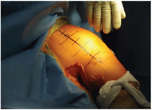 FIGURE 40-5 The deltopectoral skin approach is marked prior to placing a plastic barrier. A lap sponge is tied around the distal one-third of the humerus to aid in retractor placement later in the case. |
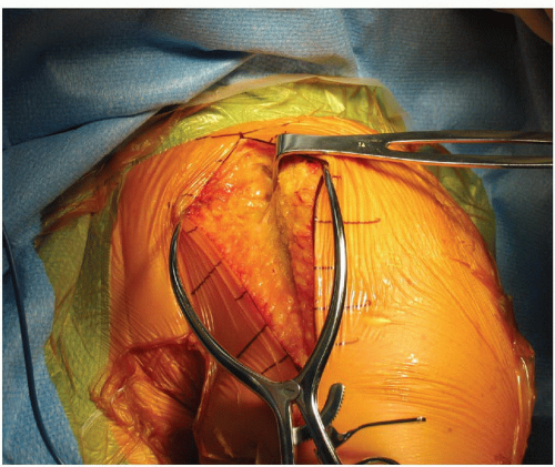 FIGURE 40-6 An Army/Navy retractor is used proximally to identify the cephalic vein. |
Approach
An extended deltopectoral approach is used for the RSP. The deltopectoral line is marked on the skin with the proximal extent of the incision starting 5 cm medial to the acromioclavicular joint and 2 cm inferior to the clavicle. The coracoid is drawn and the line follows the anterior aspect of the deltoid to its insertion on the proximal humeral diaphysis (Fig. 40-5). An incision is made with a no. 10 scalpel and a Bovie cautery is utilized to coagulate any subcutaneous bleeding. A Gelpi self-retaining retractor helps provide tension as the superficial skin dissection proceeds through the subcutaneous fat to the deltopectoral fascia (Figs. 40-6 and 40-7). The cephalic vein may be preserved or ligated, and the subdeltoid space is entered. After a bursectomy is performed, the subdeltoid, subacromial, and subcoracoid spaces are released of all adhesions so appropriate retractors facilitate exposure. Conjoined tendon is identified and retracted medially. If intact, the coracoacromial ligament can be released. A Browne retractor is placed underneath the deltoid and the long head of the biceps is identified, a tenodesis to the upper portion of the pectoralis major tendon is performed with a 2-0 nonabsorbable suture, and the bicipital groove is exposed (Figs. 40-8, 40-9 and 40-10). Self-retaining or handheld retractors are placed beneath the deltoid laterally and conjoined tendon medially. A broad, flat retractor beneath the acromion may help bring into view the superior subscapularis, if intact, the rotator interval, and superior humeral head. In patients with an intact subscapularis, it is released off the lesser tuberosity just medial to the bicipital groove permitting a circumferential release of the capsule around the humeral neck (Fig. 40-11). Atraumatic dislocation of the humeral head is performed as the surgical assistant gently externally rotates and extends the humerus (Fig. 40-12). A circumferential release of the capsule around the humeral neck is performed along with aggressive resection of osteophytes (Figs. 40-13 and 40-14).
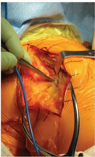 FIGURE 40-7 Dissection on the lateral aspect of the cephalic vein allows the cephalic vein to lie medially as the subdeltoid space is identified and the deltoid is mobilized from the humerus. |
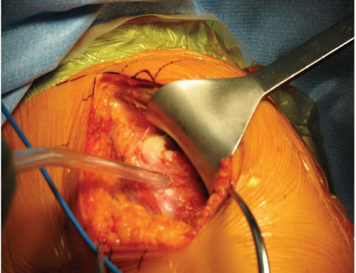 FIGURE 40-8 Browne retractor is placed underneath the deltoid. |
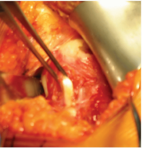 FIGURE 40-9 The long head of the biceps tendon is identified and 2-0 nonabsorbable suture is placed through the biceps tendon and through the pectoralis major tendon. Once this tenodesis is completed, the biceps tendon is transected. |
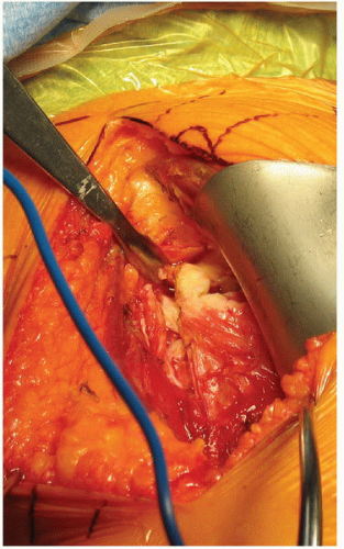 FIGURE 40-10 A sharp Hohmann retractor is placed in the proximal and anterior portion of the bicipital groove and is held in place with a clamp. |
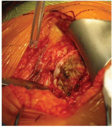 FIGURE 40-11 The subscapularis tenotomy has been performed and the inferior portion of the humeral head is exposed with the small sharp Hohmann retractor. |
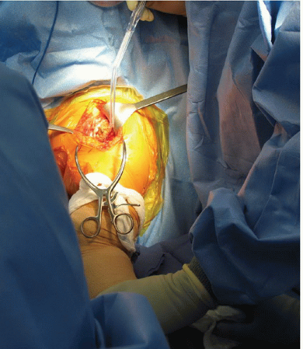 FIGURE 40-12 The patient’s humerus is externally rotated and extended on the Mayo stand as the capsular release is performed. |
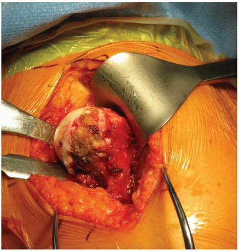 FIGURE 40-13 Multiple Hohmann retractors are placed medially and inferiorly as the humerus is externally rotated to increase humeral head exposure. |
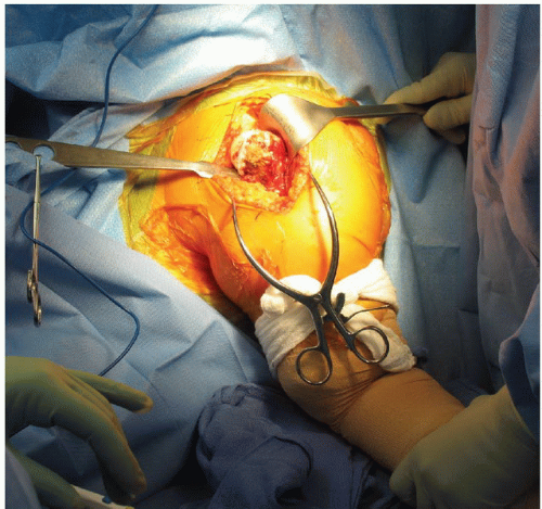 FIGURE 40-14 Once the humeral head is dislocated, osteophytes are identified and removed circumferentially. |
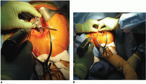 FIGURE 40-15 A: A humeral head osteotomy is performed in 30 degrees of retroversion. B: An alignment rod on the humeral head cutting guide is matched with the forearm. |
Humeral Head Osteotomy
Next, a humeral neck cut is performed in 30 degrees of retroversion (Figs. 40-15A and B, 40-16 and 40-17). The osteotomy is performed at a level that is slightly higher than the traditional arthroplasty humeral cut (Figs. 40-17, 40-18, 40-19 and 40-20). At the most proximal portion of the osteotomy, the canal of the humerus is identified with a canal finder (Fig. 40-21). A large rongeur is used to remove some metaphyseal bone around the canal opening to facilitate easy broach insertion. The humeral canal is reamed by hand. A humeral broach is then placed into the canal and sequentially broached to the desired size and left inside in the humeral shaft (Figs. 40-22 and 40-23). The proximal humerus is then reamed using the smallest metaphyseal reamer until the superior edge is flush with bony cortex (Figs. 40-24, 40-25 and 40-26). Any remaining osteophytes and a portion of the medial calcar are resected (Fig. 40-27). The humeral broach is left in position for glenoid preparation. The final metaphyseal reamers are not used until after completion of the glenoid component insertion. This technique maintains adequate humeral bone stock to support retraction during glenoid preparation while providing a sufficient resection of the proximal humerus to facilitate glenoid exposure and visualization. The subscapularis is then tagged in its most proximal superior corner and the axillary nerve is identified and palpated (Fig. 40-28). We do not routinely dissect out the axillary nerve. A small sharp Hohmann retractor is placed on the posterior aspect of the glenoid and a Cobra retractor is placed on the anterior side of glenoid neck (Fig. 40-29).
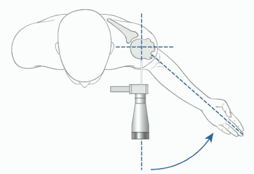 FIGURE 40-16 Thirty degrees of retroversion for the humeral head osteotomy. |
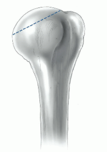 FIGURE 40-17 Humeral head osteotomy. |
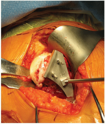 FIGURE 40-18 The height of the humeral head osteotomy is higher than for the TSA osteotomy. |
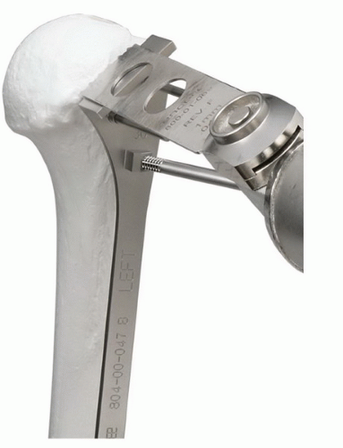 FIGURE 40-19 A saw is used to start the humeral head osteotomy. |
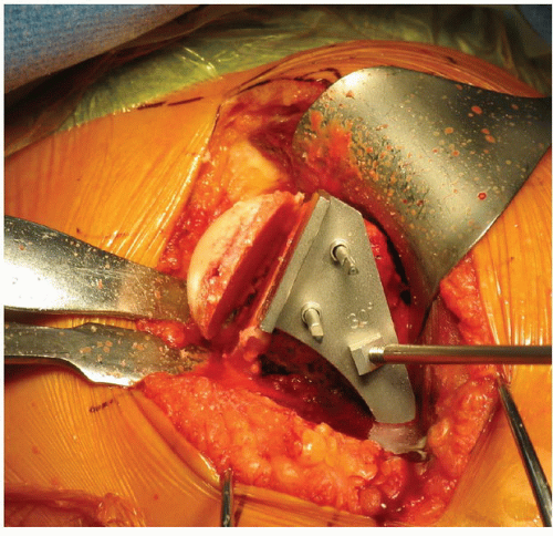 FIGURE 40-20 The osteotomy is completed with a wide osteotome. |
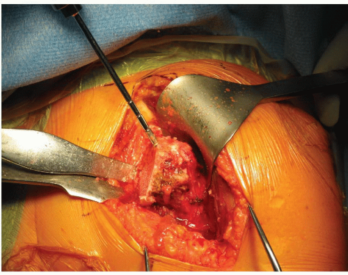 FIGURE 40-21 Humeral canal finder is placed on the midportion of the humeral osteotomy laterally. |
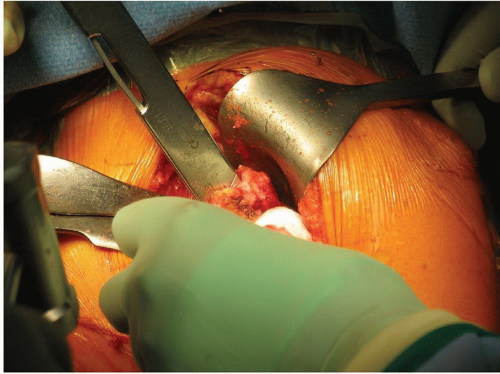 FIGURE 40-22 The broach is placed until the most proximal aspect of the diagonal line on the broach is flush with the osteotomy. |
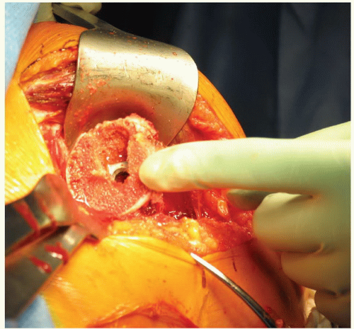 FIGURE 40-23 Humeral broach is in place in the canal. |
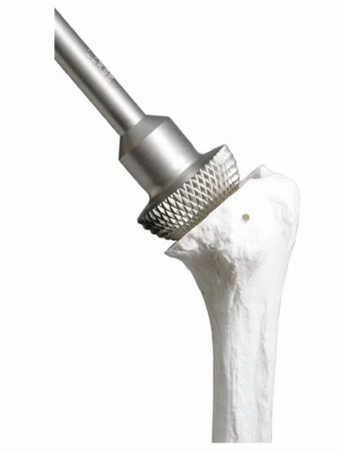 FIGURE 40-24 A model of a small metaphyseal reamer in the humeral canal. |
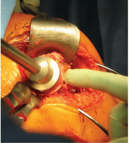 FIGURE 40-25 A small metaphyseal reamer is applied to the humerus until flush with the cortical edge. |
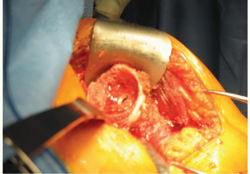 FIGURE 40-26 A reamed humeral metaphysis with broach in place. Additional osteophytes are resected with a rongeur. |
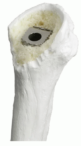 FIGURE 40-27 A model of the humerus after metaphyseal reaming and inferior bone has been removed to make a V-shape to facilitate glenoid exposure when the humerus is placed posteriorly. |
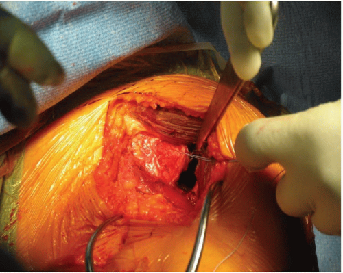 FIGURE 40-28 The subscapularis is tagged and a small sharp Hohmann is placed on the posterior aspect of the glenoid. |
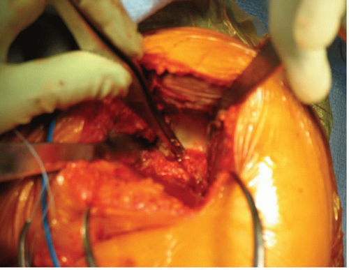 FIGURE 40-29 A small sharp Hohmann retractor is placed posteriorly and a Cobra retractor is placed anteriorly. Forceps are used to identify the capsule, which is then resected anteriorly with a Bovie cautery. |
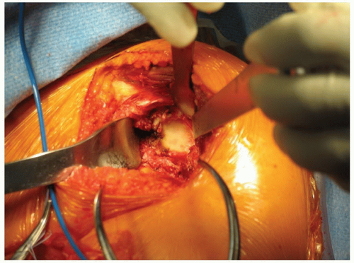 FIGURE 40-30 After the capsular release, a posterior glenoid retractor and a superior Hohmann retractor are placed to help expose the glenoid. |
Glenoid Exposure and Preparation
Glenoid exposure is accomplished by using the posterior glenoid retractor to displace the proximal humerus posteriorly. A Cobra is placed anteriorly along the glenoid neck and a Hohmann retractor is positioned on the superior face of the glenoid (Figs. 40-30 and 40-31). An aggressive 360-degree subperiosteal periglenoid capsular release is performed. The inferior capsule is carefully resected while protecting the axillary nerve. At this stage, excellent glenoid exposure should be achieved. A 2.5-mm drill is used to create a center hole for the glenoid baseplate. In a normal glenoid, one in which there has not been asymmetric wear, the location of the hole is at the center of the glenoid. When looking at the glenoid, place the drill perpendicular to the glenoid face and tilt the handle of the drill 10 to 15 degrees inferiorly (Figs. 40-32 and 40-33). This position allows preferential reaming of the inferior aspect of the glenoid; consequently, if reamed correctly, more inferior than superior bone is reamed on the glenoid. After drilling is complete, a 6.5-mm tap is used and left in place to serve as a guide for the placement of the cannulated glenoid reamers. Sequential cannulated convex reamers are used to prepare for baseplate insertion (Figs. 40-34, 40-35 and 40-36). The fixed angle hydroxyapatite-coated glenoid baseplate is then screwed into place with secure purchase. Typically, four 5.0-mm peripheral locking screws are inserted into the baseplate with the use of a locking guide (Figs. 40-37 and 40-38). If the bone is insufficient along the locked screw pathway, an option
is present to use 3.5-mm nonlocking cortical screws that can be angled eccentrically to reach better bone stock. There are multiple glenosphere options (32 mm neutral, 32-4 mm, 36 mm neutral, 36-4 mm, 40 mm neutral, 40 – 4 mm, 44 + 8 mm) from which the ideal size may be selected (Fig. 40-39). Factors such as patient size, degree of soft-tissue contracture, quality of glenoid bone, and the expected degree of instability are considerations in the selection process of the optimal glenosphere size. The glenosphere is placed on the baseplate via a Morse taper. A retaining screw is then placed into the central hole of the glenosphere to augment the Morse taper attachment to the baseplate (Figs. 40-40 and 40-41).
is present to use 3.5-mm nonlocking cortical screws that can be angled eccentrically to reach better bone stock. There are multiple glenosphere options (32 mm neutral, 32-4 mm, 36 mm neutral, 36-4 mm, 40 mm neutral, 40 – 4 mm, 44 + 8 mm) from which the ideal size may be selected (Fig. 40-39). Factors such as patient size, degree of soft-tissue contracture, quality of glenoid bone, and the expected degree of instability are considerations in the selection process of the optimal glenosphere size. The glenosphere is placed on the baseplate via a Morse taper. A retaining screw is then placed into the central hole of the glenosphere to augment the Morse taper attachment to the baseplate (Figs. 40-40 and 40-41).
Related posts:
 Arthroscopic Repair of Posterior Instability
 Arthroscopic Repair of SLAP Lesions
 Open Repair of Anterior Shoulder Dislocations and Subluxations
 Mini-open and Open Techniques for Full-Thickness Rotator Cuff Repairs
 Operative Treatment of Displaced Surgical Neck Fractures of the Proximal Humerus
 Surface Replacement Arthroplasty of the Shoulder
Stay updated, free articles. Join our Telegram channel

Full access? Get Clinical Tree


