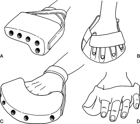
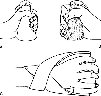
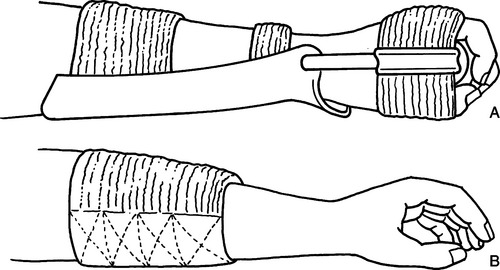
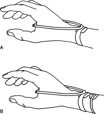
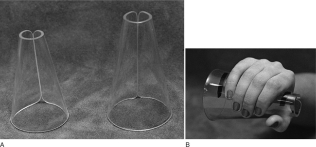
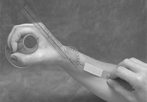
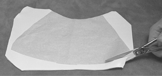
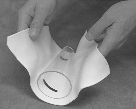
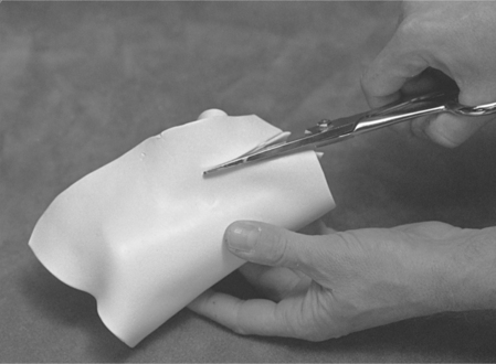
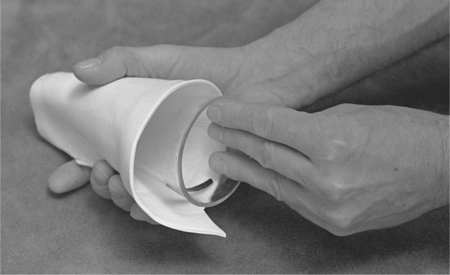
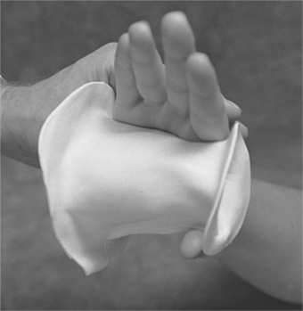
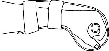
CHAPTER 14 1 Identify and describe the two historic trends in upper extremity tone-reduction splinting (orthotics). (Note: The authors use the terms splint and orthosis interchangeably in this chapter.) 2 Compare the strengths and weaknesses of dorsal and volar forearm platforms (troughs). (Note: The authors use the terms platform and trough interchangeably in this chapter.) 3 Discuss the neurophysiologic rationale supporting the use of the finger spreader and hard cone. 4 Discriminate between the passive and dynamic components of spasticity. 5 Describe the difference between submaximum and maximum ranges as they relate to tone-reduction splints. 6 Identify and describe the two major components of orthokinetic splints. 7 Describe one unique characteristic for each of the following materials: plaster bandage, fiberglass bandage, inflatable splints, cylindrical foam, neoprene. 8 Successfully fabricate and clinically evaluate the proper fit of a thermoplastic hard cone. 9 Use clinical judgment to correctly analyze two case studies. The status of tone-reduction wrist/hand orthotics is like an amorphous quicksand waiting to engulf the unwary therapist. Rehabilitation literature reflects the universal lack of consensus, which Fess et al. [2005, p. 518] summarize with the following statement: “Some physicians and therapists feel strongly that the hypertonic extremity should not be splinted, whereas others are equally adamant that splinting has beneficial results. Even among proponents of splinting, numerous disagreements exist concerning splint design, surface of splint application, wearing times and schedules, joints to be splinted, and specific construction materials for splints and splint components.” Current professional standards of practice dictate that significant cumulative data and consistent scientific analysis provide the foundation for objective evaluations and treatment protocols. Literature in tone-reduction splinting does not reflect the development of this core body of knowledge. Lannin and Herbert [2003, p. 807] conducted a systematic review of published literature on the use of hand splints following stroke and concluded that there is “insufficient evidence to either support or refute the effectiveness of hand splinting for adults following stroke who are not receiving prolonged stretches to their upper limb.” The paucity of data on the effectiveness of tone-reduction splinting has fostered confusion and contradiction. In the absence of a well-established practice protocol, this chapter is restricted to a discussion of current theoretical and experimental rationales and splint designs. Each practitioner is ultimately responsible for justifying the effectiveness of these techniques in client treatment. Basmajian et al. [1982, p. 1382] define spasticity as “a state of increased muscular tone with exaggeration of the tendon reflexes.” Clients who have upper motor neuron (UMN) lesions such as cerebrovascular accidents (CVAs), closed-head injuries, spinal cord injuries, and cerebral palsy often exhibit spasticity [Bishop 1977]. Spasticity can cause deformity [Bloch and Evans 1977] and limit functional movement [Doubilet and Polkow 1977]. Hand splinting is one treatment technique used to prevent joint deformity and influence muscle tone [Mills 1984]. Historically, experts have documented two major trends in hemiplegic hand splinting. Until the 1950s, the direct application of mechanical force to correct or prevent joint contractures (i.e., biomechanical approach) was the preferred practice in dealing with the effects of spasticity. During the 1950s, emphasis shifted to the underlying causes of spasticity. This viewpoint focuses on the effects of sensory feedback provided by splints in altering muscle tone and promoting normal movement patterns (i.e., neurophysiologic approach) [Neuhaus et al. 1981]. As differing neurophysiologic theories emerged in the 1950s, therapists advocated divergent treatment and splint management principles. At present, several prevalent neurophysiologic rationales recommend a variety of designs composed of a variety of elements related to design position and material options, including the following: (1) platform design, (2) finger and thumb position, (3) static and dynamic prolonged stretch, and (4) material properties. A forearm platform is a design element that provides a base of support to control wrist position. Many frequently used tone-reduction splint designs do not affect wrist control but attempt only to influence the digits [Dayhoff 1975, Bloch and Evans 1977, Jamison and Dayhoff 1980, Langlois et al. 1991]. Other designs attempt to influence wrist position but do not address digit position [MacKinnon et al. 1975, Switzer 1980]. Lannin and Herbert [2003, p. 807] stated that “there is insufficient evidence to either support or refute the effectiveness of dorsal or volar hand splinting in the treatment of adults following stroke who are not receiving an upper limb stretching programme.” Isolated joint control constitutes a fundamental design flaw that can produce a predictable outcome because the tendons of the extrinsic flexors cross the wrist, fingers, and thumb. If the digits are positioned in extension, the unsplinted wrist assumes a greater attitude of flexion [Fess et al. 2005]. This compensatory sequence can lead to decreased passive motion and contracture development. Rehabilitation science literature contains adherents for volar-based forearm platforms [Brennan 1959, Zislis 1964, Peterson 1980] and dorsal-based forearm platforms [Kaplan 1962, Charait 1968, Snook 1979, Carmick 1997]. Other authors report that the two positions are equally effective in tone reduction [McPherson et al. 1982, Rose and Shah 1987]. National distributors market ulnar-based platform splints designed to reduce spasticity [Sammons Preston Roylan 2005], although the literature does not appear to mention ulnar-based forearm platforms (Figure 14-1). A therapist can secure all orthotic forearm platforms to the forearm by using straps, resulting in skin contact with volar and dorsal surfaces simultaneously [Rose and Shah 1987, Langlois et al. 1989]. The corresponding cutaneous stimulation provided to flexors or extensors by the forearm platform and straps may be facilitatory or inhibitory. The literature has not yet described research that examines the exact relationship between these variables [Langlois et al. 1991]. These variables are, however, discussed later in this chapter. Figure 14-1 A hard cone attached to an ulnar platform: spasticity cone splint [Sammons Preston 1995]. A dorsal forearm platform frees the palmar area and enhances sensory feedback. This style is easier to apply and remove if wrist flexion tightness is present. Pressure is also more evenly distributed over the larger thermoplastic surface of the dorsal forearm platform as opposed to the smaller strap surface the volar style provides. An ulnar forearm platform provides a more even distribution of pressure for a client who exhibits a strong component of wrist ulnar deviation with wrist flexion spasticity (Figure 14-1). The finger spreader and hard cone are examples of splint designs based on divergent neurophysiologic treatment theories. Both positioning devices are designed to be adjuncts to specific treatment techniques that promote voluntary hand motion [Bobath 1978, Farber 1982, Davies 1985]. The neurodevelopmental treatment (NDT) theory advocates the use of reflex-inhibiting patterns (RIP) to inhibit abnormal spasticity. Finger and thumb abduction is a key point of control that facilitates extensor muscle tone and inhibits flexor muscle tone [Bobath 1978, Davies 1985]. The finger-spreader design assists in maintaining the reflex-inhibiting pattern. Therapists have constructed recent adaptations of the finger-spreader design from rigid thermoplastic material [Doubilet and Polkow 1977, Langlois et al. 1991]. Bobath’s [1970] original soft foam material has dynamic qualities that are sacrificed when the therapist substitutes rigid, more durable, and cosmetically appealing materials [Langlois et al. 1989] (Figure 14-2). Doubilet and Polkow [1977] state that positioning the thumb in palmar abduction with the metacarpophalangeal (MCP) and proximal interphalangeal (PIP) joints extended is preferable to radial abduction of the thumb because palmar abduction provides greater fitting security, positions the thumb more comfortably, and produces similar results in spasticity reduction. In addition to deciding the thumb position, the therapist considers wrist and interphalangeal joint control. Although some researchers have not extended their RIP designs to include the wrist or interphalangeal joints [Doubilet and Polkow 1977, Langlois et al. 1991], other experts have included extension of the interphalangeal joints of the fingers, thumb, and wrist [Snook 1979, McPherson et al. 1985, Scherling and Johnson 1989]. The resulting design provides a continuous chain of stabilizing forces throughout the wrist and digits. This chain is necessary to prevent compensatory patterns that transfer the forces of spasticity to the unsplinted joint. Rood [1954] first advocated the inhibition of flexor spasticity by using a firm cone to provide constant pressure over the palmar surface. The device should provide skin contact over the entire palmar surface for maximal effect but should not apply stretch to the wrist and finger flexor muscles. Farber and Huss [1974] observed that the hard cone has an inhibitory effect on flexor muscles because this device places deep tendon pressure on the wrist and finger-flexor insertions at the base of the palm. Farber [1982] also observed that the total contact from the hard cone provides maintained pressure over the flexor surface of the palm, thus assisting in the desensitization of hypersensitive skin. Hard cones are typically constructed of cardboard or thermoplastic material (Figure 14-3). This hollow structure is positioned with the smaller end placed radially and the larger end placed ulnarly to provide maximum palmar contact. Kiel [1974, 1982] recommends the provision of a thenar groove to relieve web-space pressure. Design criteria for hard cones as cited in the literature does not include the use of forearm platforms to control wrist position. Although Kiel [1974] uses a volar platform with a hard cone in the orthokinetic wrist splint (Figure 14-4), the movable wrist joint allows free motion to occur in wrist flexion and extension. Hard cones attached to ulnar platforms (Figure 14-1) are commercially available [Sammons Preston Rolyan 2005], but the literature does not appear to discuss the combination of forearm platforms and hard-cone elements designed to control wrist and finger position. When using a firm cone without a forearm platform, the therapist secures the cone to the hand by using a wide [e.g., 2.5-cm (1-inch)] elastic or nonelastic strap over the dorsum of the hand (Figure 14-4) [Dayhoff 1975, Jamison and Dayhoff 1980]. Dayhoff [1975] reports that contact with soft material on the palmar surface appears to increase flexor tone. This soft stimulus may activate the primitive grasp response [Farber 1982]. Brunnstrom [1970] describes this response as the instinctive grasp reaction. Commercially available soft-palm protectors [Sammons Preston Rolyan 2005] may be contraindicated for clients who exhibit the primitive grasp reaction. MacKinnon et al. [1975] adapted the standard hard cone to increase sensory awareness and improve hand function. They altered the design from a 4- to 5-cm diameter hollow cone shape to a 0.3- to 1.3-cm diameter cylindrical shape by using a solid wood dowel. Placement of the dowel is critical to design rationale. Pressure over the palmar aspect of the metacarpal heads may be a key to activating hand intrinsics. In response to increased intrinsic activity, muscle tone is reduced in finger flexors and the thumb adductor. Placement of the dowel more distally shifts the maximum contact area from the palm to the metacarpal heads and exposes a larger palmar surface to sensory feedback, thus enhancing awareness and use of the hand. The original MacKinnon splint incorporates a dorsal forearm platform consisting of a small rectangle of thermoplastic material attached to the dorsum of the wrist with a volar Velcro strap [MacKinnon et al. 1975]. This platform serves as the base for plastic tubing secured to the palmar dowel. The intention of this platform is not to position the wrist forcefully in extension but to position the dowel to apply maximal pressure to the metacarpal heads. Exner and Bonder [1983] enlarged this dorsal forearm platform because it was insufficient to control the forces of marked wrist flexion spasticity. The design alteration relieves skin pressure, provides increased wrist control, and ensures greater comfort (Figure 14-5). 1. Determine the correct cone size by positioning an acrylic cone in the client’s palm. (Use a small Sammons Preston BK-1500 or a large BK-1502 acrylic cone, as shown inFigure 14-6A.) The therapist must establish the correct amount of palm pressure the client can tolerate without application of stretch to the fingers and thumb. Slide the cone onto the client’s hand to determine the correct position (Figure 14-6B). 2. Establish the wrist position by using a goniometer to measure the submaximum or maximum amount of wrist extension the client can tolerate. This measurement must take place while the client wears the acrylic cone (Figure 14-7). Mark on the material the medial and lateral borders of the hand while the cone is positioned in the palm (Figure 14-6B). 3. Using the template provided (Figure 14-8), trace and cut out the pattern from thermoplastic material (Figure 14-9). 4. Apply dishwashing liquid to the acrylic cone as a parting agent. 5. Wrap heated thermoplastic material around the cone (Figure 14-10). 6. Using a sharp pair of scissors, cut the place where the material meets to create a smooth seam edge (Figure 14-11). 7. Slide the thermoplastic cone off the acrylic cone before the material cools to prevent removal difficulty (Figure 14-12). 8. Fit the thermoplastic cone to the client’s hand (Figure 14-13), and mark the following on the cone.
Antispasticity Splinting
Forearm Platform Position
Finger and Thumb Position
Cones
Hard-Cone Splint Construction for the Wrist and Hand
Related posts:
![]()
Stay updated, free articles. Join our Telegram channel

Full access? Get Clinical Tree


Antispasticity Splinting